This thread has been locked.

If you have a related question, please click the "Ask a related question" button in the top right corner. The newly created question will be automatically linked to this question.

UCC28881 isolated flyback solution to output 5V@500mA

Other Parts Discussed in Thread: UCC28881, PMP10143, UCC28880, PMP, TL431

Hi Team,

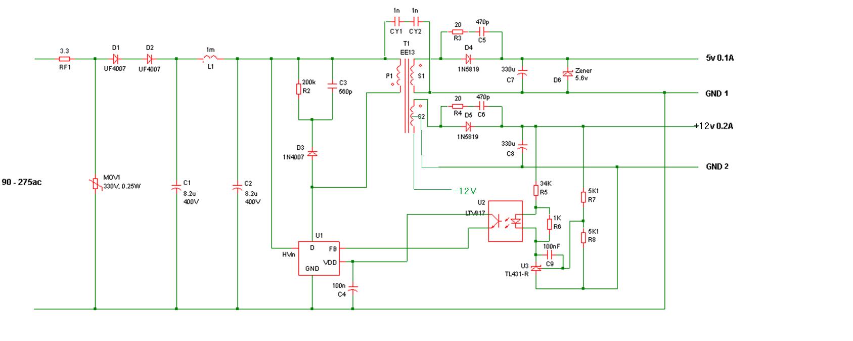
Is there any reference design using UCC28881 to converter 90-264VAC to 5V@500mA in isolated flyback topology?

There is a reference circuit on data sheet page 25 but customer need detail component values and transformer spec.

Thanks and best regards,

Victor

  • Victor,

    You could take a look at PMP10143:
    www.ti.com/.../PMP10143

    This is a 1.7 W design using UCC28880. This is a dual output, 3.3 V @ 0.4 A & 12 V @ 0.03 A.

    For your requirement, you could change to the UCC28881, remove the 12 V output, and modify the 3.3 V rail to get 5 V (more sec turns, higher voltage rating rectifier diode, etc).

    I hope this is helpful for you.

    Thanks,
    Bernard
  • Hi Bernard,

    My customer accepted the solution but some spec has changed end customer side.
    The new requirement are as following:
    1. Universal Input
    2. Half wave rectifier input
    3. 2 output, one isolation 5V 150mA, and the other is non isolation 3.3V 75mA

    The reason why two outputs and one is non-iso is because then end customer has a metering IC which must be non-isolation and the DC ground should connect to Neutral.

    Could you please suggest how to modified the above PMP circuit using UCC28880?
    Thank you very much.

    Best regards,
    Victor
  • Victor,

    If you browse through the available TI-Designs and refernece designs on the UCC28880 and UCC28881 product pages (look under "Tools & Software" where you will see listed all simulation modesl, design assisitance calculators, and released reference designs), you will see many other designs, where there might be a better fit for the revised spec.

    E.g. TIDA-00708 uses UCC28881 for a 5-W dual output Flyback:
    www.ti.com/.../TIDA-00708

    This is AC input, with an isolated 12-V output and a non-isolated 12-V output, plus a 4-V output with LDO for 3V3. You could modify this one to eliminate the non-isolated 12-V and the LDO, and take the FB directly from the 3V3 non-isolated rail. Then the isolated 12-V rail could be changed to lower number of turns for 5-V output. If the power in this case is lower, the UCC28881 on that design could be changed to UCC28880.


    I hope this helps.

    Thanks,
    Bernard
  • Hi Bernard,

    Thanks a lot. The reference should be fine to customer.
    By the way, since it will be half wave rectifier AC input, is there anything needs to be done in the input rectifier circuit, such as modifying the caps and instructors? The average input voltage will be half compare to full wave AC voltage and the reference design just shows 100V-450VDC.

    Best regards,
    Victor
  • Victor,

    Yes you are correct, for half-wave rectified input, more bulk capacitance would be required to achieve the same peak-peak ripple voltage at the input. Since TIDA-00708 is designed for DC input, it only uses a very small input capacitance.

    For full-wave rectified, typical bulk cap value is ~2 uF/W. In this case, total output power is ~1 W, so aloow ~1.5 W input power (depends on eff). So about 3.3 uF is probably a good value for full-wave input. Half-wave would need at least 2x to 3x this value, so 10 uF sounds like a reasonable value to start with. If the minimum ripple voltage is too low, you will need more input cap.

    I hope this helps answer your question.

    Thanks,
    Bernard
  • Hi Bernard,

    Customer has finished the schematic and transformer design. Could you please help to take a look and give some advise for optimisation? Thank you very much.

    Spec:

    1. Universal input
    2. Output 1 non isolation 5V 0.1A (no feedback control)
    3. Output 2 isolation 12V 0.2A (with feedback control)
    4. Output 3 isolation -12V

    Schematic: 

    Transformer spec:5v 0.1A, 5v 0.2A TRF.PDF

    Please note that the transformer winding N3=S2 will change to 48T with center tap.

    Thanks and best regards,

    Victor

  • Victor,

    For half-wave rectification with 16-uF bulk cap, I estimate that the minimum bulk cap ripple will be about 70 V. So the transformer needs to be designed for this minimum input voltage at 45% Dmax (w.c. min). This means that the reflected voltage will be limited to about 57 V. This means the transformer turns ratio from prim to main 12-V winding should be about 4.6:1, but the customer design is actually 8:1 right now. They need to change the turns ratio, or increase bulk cap min voltage level.

    If the customer wants to keep ~100 V reflected voltage, then they will need to change to full-wave rectified, and probably also increase the bulk cap value to about 27 uF. If they keep half-wave rectified input, they will need at least about 33 uF to keep min bulk cap voiltage above 100 V.

    The transformer magnetising inductance is too high, this will not be able to ramp the current up to the required peak value.

    Following the calculation method on page 8 of TIDA-00708 design document, assume Pin = 5 W (3 W output @ 60% eff w.c.).

    At 70 V min bulk voltage, Iin_avg = Pin/Vmin = 5/70 = 71 mA.

    Iin_pk = (Iin_avg * 2) / Dmax = (71 mA * 2) / 45% = 317 mA - the UCC28881 Ipk w.c. min is 315 mA, so we can just about meet the 5-W input power required.

    Lpri = (Vmin * Dmax) / (Ipk * fmax) = (70 * 0.45) / (0.315 * 52 kHz) = 1.92 mH


    On the sch, here are some points:
    - the -12 V rail will need a rectifier and cap
    - what is the load on the -12 V rail? I have assumed total outptu power ~ 3 W max.
    - a pull-down resistor Rfb should be added to FB pin
    - a filter cap option should be added in parallel with Rfb in case it is needed later
    - R7/R8 values are not correct for 12-V output
    - R5 value need to be calculated together with Rfb value to set 1-V level at FB pin. With R5 = 34k, max TL431 current ~250 uA. Assume opto w.c. min CTR ~ 25% => Ifb ~ 62 uA. Vfb ~ 1.1 V = > Rfb ~ 18 k
    - D5 (and diode for -12 V rail) need to have higher voltage rating. For Nps = 4.6, Vmax across diode ~ 400/4.6 + 12 = 99 V => use 150-V diode. For Nps = 8, even higher rating is needed


    Bernard
  • Hi Bernard,

    Thanks a lot for the detail calculation. Let me summary a bit.
    Transformer:
    1. Change input bulk cap to 33uF and keep turn ratio 8:1
    2. Reduce the primary side N1 to about 113.5 turns. Lpri = (Vmin * Dmax) / (Ipk * fmax) = (100 * 0.45) / (0.222 * 52 kHz) = 3.90 mH, 192/(6.6mH/3.9mH) = 113.5
    3. Reduce N3 to 28 turns with center tap.
    4. Reduce N2 to 5.9 turns.

    Schematic:
    1. -12V add rectifier and cap
    2. The load on -12V rail is about 10mA - 30mA. There is margin of current on all rails so the actual output power should be less than 3W.
    3. Add pull-down resistor Rfb = 18k to FB pin and place for cap in parallel with the Rfb.
    4. Change R7 : R8 to 3.8 : 1
    5. D5 and -12V rail diode can be 100V, 400/8+12 = 62V
  • Victor,

    If the customer increases the bulk cap value to ensure that Vmin >= 100 V, then the turns ratio 8:1 can be used.

    If the Dmax of 45% is used at Vmin = 100 V, this gives Ipk ~ 222 mA, then Lpri ~ 3.9 mH as you also calculated above.

    Your calculation of the required turns is incorrect - inductance scales with turns-squared, so the ratio of turns will be the square-root of ratio of inductance:

    L1/L2 = (N1^2 / N2^2) = (N1/N2)^2 => N1/N2 = (L1/L2)^0.5 = > N2 = 192 / (6.6/3.9)^0.5 = 148

    However, this may not be the correct approach since the peak current is also changed.


    It's better to explicitly verify the peak flux-density in the core, Bpk.

    The drawing say that EE13 core set is used, but the Ae and core dimensions are not listed. Is this E13/6/6 or E13/7/4 size that is used? Because they have different Ae values.

    The required turns will really depend on the target Bpk level in the core, which depedns on the customer spec/preference.

    Bpk = (L * Ipk) / (N * Ae) => N = (L * Ipk) / (Ae * Bpk)

    In this case, if Ae = 20 mm^2 (E13/6/6), and if Bpk ~0.3 T (for inductors and flyback transformers, often the Bpk is pushed a bit higher to minimise turns and Cu loss):

    N1 = (3.9 mH * 0.222 A) / (20 u * 0.3) = 144

    => N2 =7 or 8 , N3 = 18+18 (36 with centre-tap) - will need to adjust turns to get closer to exact 12/5 ratio between N3/N2.


    For rating of D5 and diode on -12-V rail, 100-V rating would be needed with 8:1 turns ratio - the 1N5819 part on the sch is only 40-V rating.

    Thanks,
    Bernard