This thread has been locked.

If you have a related question, please click the "Ask a related question" button in the top right corner. The newly created question will be automatically linked to this question.

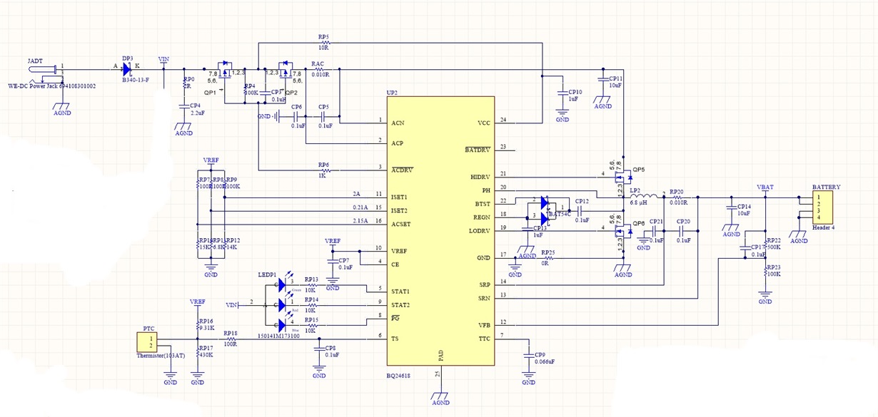
Need help with my li-ion charger circuit (bq24618) with 5V output.

Hi
I need your opinions and help about my circuit design. Here below is my projects charger part scheme. I am not a electronic engineer and not much experienced in electronics so i advised by an EE during design.
Circuit using TI's BQ24618 IC.

I want to use this circuit to charge 4s2p Li-ion (3.7V 3000mAh samsung 18650 * 8 Li-ion batteries so 14.8V and 6000mAh) battery pack with 20V 2A wall adapter. Battery pack has included protection PCM.
I printed and soldered PCB. Here is my problems.
Charger circuit acting as charging. green led (stat1 ) and blue led (PG) on. But never complete charge after hours (theoretically green led get off and red led - stat2 - get on when charge completed is not it? ) Also the circuit was cold during all charging process so i think cirucit is not working.

Then I realised the resistance RP22 is wrong. RP22 must be arround 700K for charging 4 cell . I tought that i designed the circuit wrong and this circuit can be use for 3 cell li ion. So i tried to charge a 3s2p li ion battery pack. That time i quess circuit is working. A little heat on circuit. After a couple hours green and blue light started to blink. So I thought the circuit is failing again am I wrong ? 

Also circuit has a LM2476-5.0 part with usb output for charging cell phones or etc.

When i attached battery pack to Circuit it seems i can get 5v from USB output. I can power up an arduino or teensy. But i can not charge an iphone from USB ? What can be cause problem?

Can you please evaluate the circuit design and give me advices? Any advices, opinions, helps needed.

Thank you very much.

  • Jud,

    You are correct about the voltage divider - a Li-Ion cell typically charges to 4.2 V, making 700k Ohms the correct resistor in your feedback divider. 

    You are trying to charge a 6000mAh battery with 2000mA (0.3C). Ideally, this would take 3 hours to fully charge your battery. If you are using a 2A adapter, that does not leave much room for error. It is possible that you are "crashing" the adapter and causing it to regulate poorly. This in turn could cause the blue (Power Good) pin to change like it is. You can try and get a higher current adapter and see if that fixes the issue. 

    Have you ever done PCB layout before? It may seem simple at a glance, but doing it correctly can be tricky. If you have not done so, adding a ground plane will add more copper mass to dissipate heat. If your high current traces are too narrow, that can also cause a temperature rise(as well as risk burning out your trace, much like a fuse).

    As far as charging the iphone with USB, I see that you are just giving it +5 V and GND. If you are not doing anything with the D+ and D- pins, it is most likely setting the charging current to a minimum, or not at all depending on what the phone is expecting.

    A quick google search gives this explanation for the USB pins on an iphone 5: http://www.voltaicsystems.com/blog/choosing-usb-pin-voltages-for-iphones-and-ipads/

    This should be able to serve as a starting point, but charging over USB is not a trivial task. If you head over to the connectivity forum for E2E, there are members of the forum much more experienced with USB than I am that should be able to give you better quality help with the USB portion of your project. 

     
    VBUS
    I_BUS  (meas IBAT)
    ACP-ACN
    I_ADP (20x)
    PSYS
    0


    25


    ?


    85


    VSYS
    I_SYS (meas IBAT)
    ACP-ACN
    I_BAT (16x)
    PSYS
    0


    25


    ?


    85