This thread has been locked.

If you have a related question, please click the "Ask a related question" button in the top right corner. The newly created question will be automatically linked to this question.

TPS7A33 Issue

Other Parts Discussed in Thread: TPS7A33

Hi,

I have designed a TPS7A33 test board according to the layout and recommendations of the datasheet but after soldering the output of the regulator was not regulated. It's valuable to say that at first I have set Css/nr to 1uF. In this case the output descent from desired voltage to about 0V in about 1 minute. When I changed this capacitor to 10nF, the outputs follows the input voltage and after a while the output jumped to zero and now it is always zero even after turning input on and off. 

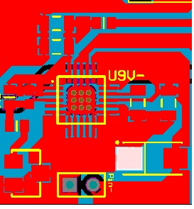
I have used the vqfn package. I have soldered two different boards but none of them work correctly. After this I have checked another IC. The thermal pad is not connected internally to the GND of IC but in the datasheet, it is indicated that it is connected internally to the ground. Anyway, in my layout, thermal pad is connected to a large GND plane. Below you can fine the layout. Please help me!

  • Hi ,

    The PCB layout looks ok from what I can see. When you are testing the IC, are you able to isolate the LDO from downstream devices? Also unintentional leakage paths (such as flux) can cause unexpected behavior.

    Very Respectfully,
    Ryan
  • Hi
    Thanks for your reply.
    The LDO is isolated from the other sections of circuitry as you have mentioned.
    I guess the origin of the problem was the material that the boards were cleaned by it. We have used methyl alcohol 99.96%. I soldered another PCB and measure the output voltage, it has oscillation around desired voltage, then I cleaned the board with alcohol and after that the output goes to zero. I cleaned the board with a kind of tuner spray that contains fast paint thinner and baked the board in 400'C for 30 seconds the board start working to some extent.
    By some extent I mean the output start from desired voltage but gose bellow that for about 400 mV in 1 minute (instead of -9 V it goes to -8.54 V). (I have considered Vref range)
    Moreover I wonder to know if connection of thermal pad and ground on PCB is not OK what would happen?
    And if you can say anything about right soldering procedure (allowed temperature and time) I will be so glad.


    Best Regards

    PS: about Cnr/ss what is a good choice and what are the criteria to choose proper value? (I don't have startup issue) in the datasheet I can see several values for that in graphs, in ac performance section it is mentioned that 100 nF is proper, but its figure shown its value 1 uF while in noise performance it is 10 nF ???

  • Hi ,

    Here is an Application Report discussing Handling and Process Recommendations:


    All internal voltages are measured with respect to the voltage on GND.  If a proper GND connection is not made, the output could appear as if it is floating.  Due to the fact that an LDO will not generate a higher voltage on OUT than IN, Vout will still be limited by the input power supply.  As such Vout could be any voltage between the input supply ground and Vin without a proper ground connection of the LDO.

    The value of Cnr/ss is application dependent.  This capacitor has two purposes.  First it will act as a soft-start capacitor; therefore, for some application the size will be determined by the startup time desired.  Second this cap acts as a noise reduction capacitor.  The datasheet contains several characteristic curves that show the effect Cnr/ss has on AC conditions.  Please note that per the Recommended Operating Conditions Table, 1uF is the recommended value for Cnr/ss.

    Very Respectfully,

    Ryan

  • Thanks for your fast and kind answer.