This thread has been locked.

If you have a related question, please click the "Ask a related question" button in the top right corner. The newly created question will be automatically linked to this question.

Using TL1431-Q1 with 126V supply for Crowbar Circuit

Other Parts Discussed in Thread: TL1431-Q1, TL1431

Hello,

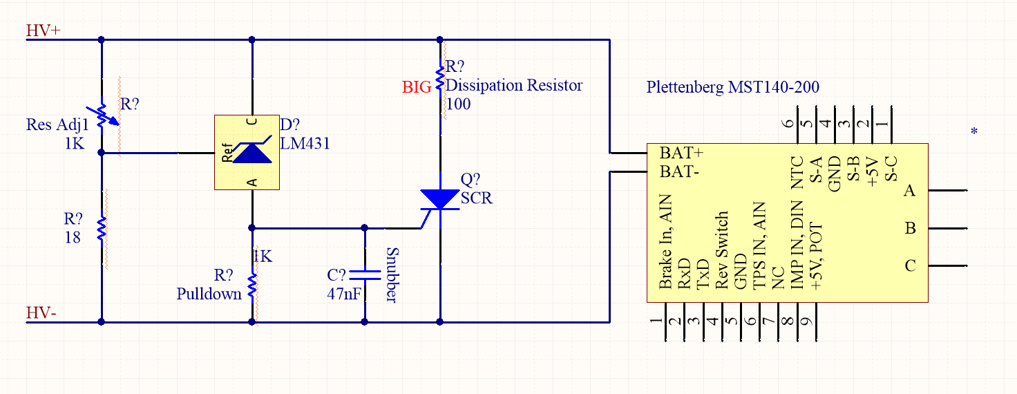
I am designing a crowbar circuit that is supposed to activate in the event that the motors are running and a safety contactor opens and cuts power to the controllers. Vmax for the DC bus is 126V so I want to sense 110% of Vmax which is ~140V. I am leaning away from a regular Zener because of the temperature dependence and the 5% tolerances. This circuit cannot accidentally trip! I figured this shunt reference (TL1431-Q1) would work well, but I see the max cathode voltage is 36V. Should I add a large power resistor on the cathode line to drop the 90V so Vdd is 36V?

Thanks!

  • Hello Jason,

    In general, this will not work because the voltage from the anode to the cathode is far in excess of 36V as you mentioned.
    I see that you have a dissipation resistor for the SCR, I believe you are referring to a similar resistor for the TL1431?

    Unfortunately, the TL1431 will not be conducting most of the time (when the voltage is at a normal level) and since it isn't conducting, even if you put a resistor there will be a large voltage across the cathode to anode.

    I am thinking about a good solution to solve this problem, and will get back to you soon.

    Best,
    Michael
  • Thanks for the response Michael.

    That's what I thought as well. No current through that resistor = no voltage drop = high voltage differential across chip = magic smoke

    The dissipation resistor is to provide a load to dissipate across so the motor controller terminals aren't directly shorted when the crowbar circuit is activated. 

    I look forward to hearing what you come up with. I will continue brainstorming as well.

  • Hello Jason,

    You should be able to implement the following circuit, but would be good to test it out.

    The NPN protects the TL1431 from the full voltage and the three resistors set the cathode voltage and the point at which the reference voltage exceeds 2.5V based on 140V. I believe the one below is set to about 130V, but you could tweak the resistor ratios to get 2.5V on the reference when the output is 140V.

    Best,
    Michael

  • And here is a suggestion for the NPN: 2SD2438
  • Hi Michael,

    Thanks for the circuit.  I have a couple questions...

    1. Could you elaborate on how the NPN protects TL1431 from the full voltage? 
    2. Just so we're clear, for setting the voltage to 140V, we would use the equation Vout = Vs * R3 / (R3+(R1+R2)) where Vout = 2.5V and Vs = 140V
    3. And then R5 is a pulldown resistor for the Silicon Controlled Rectifier, correct?

    Best Regards,

    Jason

  • Hello Jason,

    1. The emitter of the NPN transistor is a diode drop below the base, so if the resistors are set properly, then the base of the NPN should be within the maximum Vka of the TL1431, and therefore the emitter, which is connected to the cathode of the TL1431, will be within the maximum Vka of the TL1431.

    2. Yes, you are correct.

    3. Yes, R5 is a pulldown resistor for the SCR for the crowbar circuit.

    Hope this helps! Let me know if you have further questions.

    Best,
    Michael