This thread has been locked.

If you have a related question, please click the "Ask a related question" button in the top right corner. The newly created question will be automatically linked to this question.

LM5116 No Switching of HO/LO

Other Parts Discussed in Thread: LM5116

Hi,

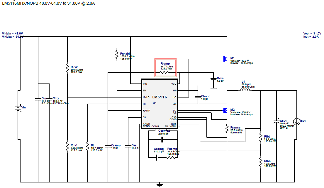
I have designed a DC/DC converter using the LM5116 by simulating it with the webbench tool according to following specifications:

IN: 48...80V

OUT: 31V, 3A, high inductive load.

The VCCX pin is connected to an internal DC/DC converter with 12V supplied by the output voltage of this LM5116. Additionally to the design below, the UVLO input is connected to a 1uF cap to GND and a diode connected to VIN. During normal start-up conditions, the VCCX voltage is present ~50ms after start-up but are nut present on those units, of course.

I have currently 2 defective units with no switching of the output. They have operated several hours and failed suddenly. Unfortunatelly I have not recorded any data during the fault conditons.

Please see the measurements on each pin below for the units:

VIN = 56.1V, EN = 38.2V, RT/SYNC = 1.21V, RAMP = ~4mV, FB = 54mV, DEMB ~1mV...6mV, CS+CSG = ~1mV

VOUT = 696mV...900mV, LO = ~1mV, SW = 696mV...900mV, HO = 696mV...900mV, HB = 7.0...7.2V, VCC = 7.2...7.3V, VCCX = ~3mV

With a replaced LM5116 the rest of the circuitry works well, so only the LM5116 part is not working.

Do you have any suggestion why the controller does not drive the MOSFETs and not producing any output voltage?

Any fast response is highly appreciated.

  • Hello,

    Please forward the schematic.

    Regards,

    Tim

  • Hello Tim,

    please see attached the schematic.

  • Hello Tim,

    further questions to the LM5116 design:

    The datasheet recommends a resistor to VCC at PIN "RAMP":
    "For higher output voltages, additional slope compensation may be required. In these applications, a resistor is added between RAMP and VCC to increase the ramp slope compensation."
    Can you give me some recommendations how to calculate this resistance?

    What is the maximum rating at this pin, because the datasheet defines this pin as an input:
    "RAMP, COMP are output pins. As such they are not specified to have an external voltage applied."
  • Andreas,

    Can you provide the UVLO voltage? And can you also confirm that EN is really 32V? Provided the schematic is correct , VIN = EN voltage.

    -Garrett
  • The ramp resistor calculation can be found in section 8.2.2.16.1 of the datasheet.
  • Hello Garrett,

    Q:Can you provide the UVLO voltage? And can you also confirm that EN is really 32V? Provided the schematic is correct , VIN = EN voltage.

    A: The EN pin is about 38V, see table below. The UVLO pin is 0V at two units and 1.62V at one other unit.

    The failures of the units are similar: No gate drive and therefore no output voltage.

    Do you have suggestion what could be the root cause?

    The screenshot I attached below is the start-up of the failed unit with the 1.62V at the UVLO pin.

    VCC

    >4.5V

    UVLO

    >1.215V

    EN

    >3.3V

    HO, LO, SW

    Comment

    0

    0.064

    38.2

    0.718

    No Gate Drive

    7.22

    1.62

    38.7

    0.696

    No Gate Drive

    7.34

    0.065

    34.4

    0.900

    No Gate Drive

    Q: The ramp resistor calculation can be found in section 8.2.2.16.1 of the datasheet.

    A: The ramp calucation was done according the datasheet:

    VOUT = 31V

    IOS = 31V / 3 * 10µA/V = 103µA

    VCS(TH) = 0.11V; VCS(THX) = 0.12V

    RS = 0.11 / (5A + (31V / (280kHz * 68uH) = 16.6mOhm @5A; 19.5mOhm@4A

    RS = 0.12 / (5A + (31V / (280kHz * 68uH) = 18.1mOhm @5A; 21.3mOhm@4A

    CRAMP = 103uA * 68uH / (31V * 10V/V * 20mOhm) = 1.13nF à 1.2nF

    VRAMP = (5uA/V * (VIN-VOUT) +25uA) * (tON /CRAMP) = (5uA/V * (56-31)+25uA)*(2.4us/1.2nF) = 0.3V

    VRAMP = (5uA/V * (VIN-VOUT) +25uA) * (tON /CRAMP) = (5uA/V * (56-31)+25uA)*(4.0us/1.2nF) = 0.5V

    VOUT > 7.5V:

    RRAMP = (12V - VRAMP) / (103µA - 25uA) = (12V-0.3V)/78uA = 150kOhm

    RRAMP = (12V-0.5V)/78uA = 147kOhm

    The results of the Webbench-Simulation was 88.7kOhm, so I used 91kOhm instead of 150kOhm.

    The screenshot below is the power down of a working unit. One channel 1 you can see the peak after switching of the device. Can this voltage spike of about about 800mV (or higher) damage the part?

  • Andreas,

    In the first schematic that you provided it shows that you are using the VCCX pin. In all the test above are you using the external 12V supply that is indicated? If so the VCC voltages should be 12V. 

    Also, In the below waveform UVLO should follow VIN because it is connected by resistor divider. Did you change the schematic at some point?

    The peak on RAMP during shutdown should not be an issue.

    -Garrett

  • Hello Garrett,

    Q: In the first schematic that you provided it shows that you are using the VCCX pin. In all the test above are you using the external 12V supply that is indicated? If so the VCC voltages should be 12V. 

    A: This is acutally the issue with the failed units. Because the IC does not work as specified (no output because of no switching of the external MOSFETs) there is no voltage at VCCX and the controller uses the internal voltage during start-up. Typical time for a working unit is 20ms from swithcing on until the 12V supply is active and can supply the controller at the VCCX pin.

    All units decribed in the table below do not start because of different reasons (EN, UVLO, VCC), but each of them are build in identical electronics with the same schematics.

    VCC

    >4.5V

    UVLO

    >1.215V

    EN

    >3.3V

    HO, LO, SW

    Comment

    0

    0.064

    38.2

    0.718

    No Gate Drive

    7.22

    1.62

    38.7

    0.696

    No Gate Drive

    7.34

    0.065

    34.4

    0.900

    No Gate Drive

    Q: Also, In the below waveform UVLO should follow VIN because it is connected by resistor divider. Did you change the schematic at some point?

    A: There is no change to the schematics. This is one of the odd behaviour of the failed units.