Hello,
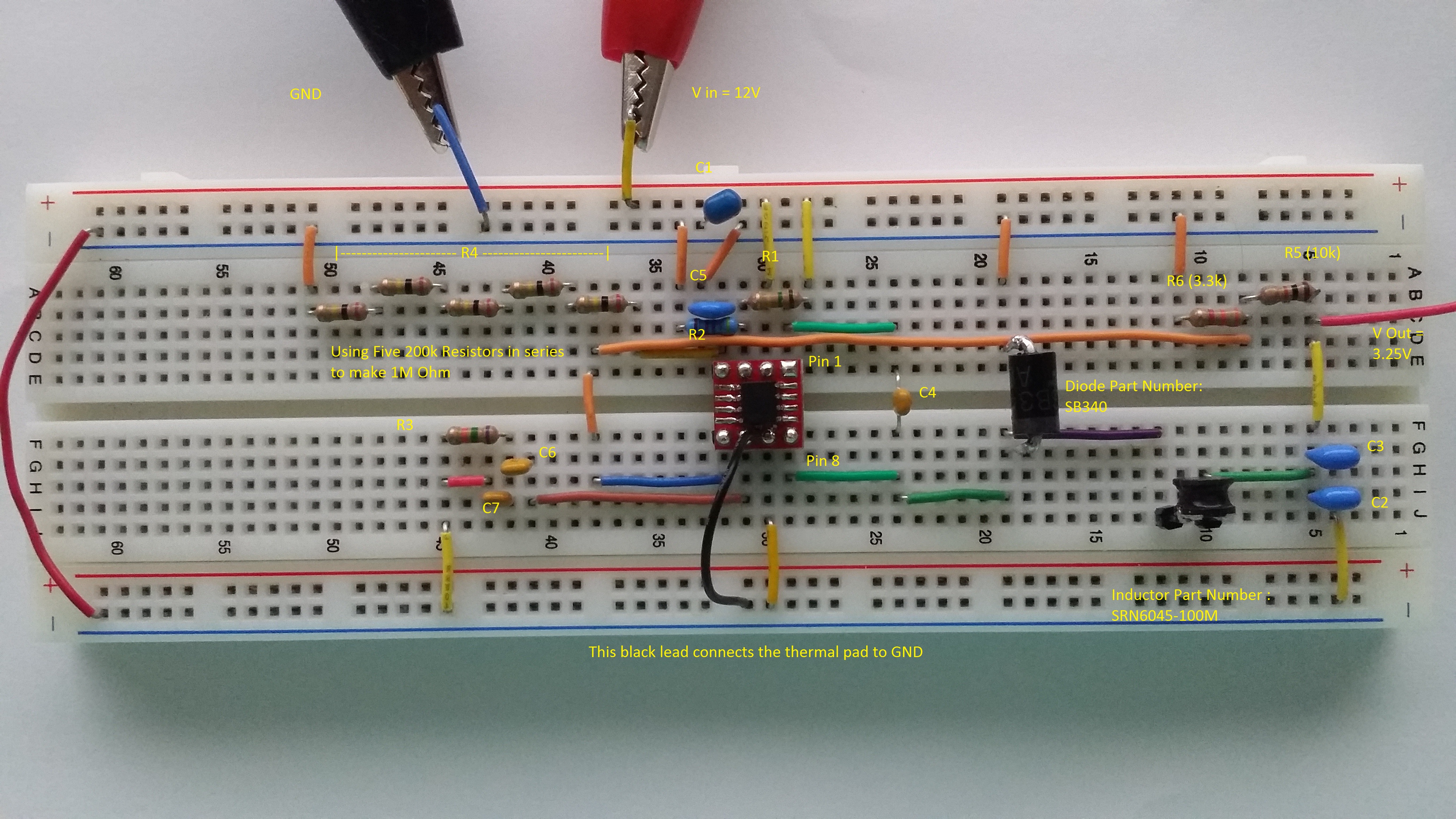
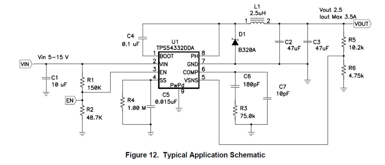
I built a prototype circuit using the TPS54332 on a breadboard. I precisely followed the typical application schematic (Figure 12 in the datasheet) while making this circuit. The only component values that deviated from the typical application schematic were those of the inductor and of the two resistors that control the voltage. I selected these resistors to adjust the output voltage to 3.25V.
My intention was to draw approximately 1.5A of current from the regulator by connecting the regulator's output to a 2-Ohm resistor. However, once the load was connected, the regulator delivered the current only for a maximum of around eight seconds before it failed. When it failed, the output voltage matched the input voltage.
I have scoured my breadboard for errors in the connections, but I have found none so far.
My only hypothesis about this situation attributes the regulator's failure to the inductor. The inductor that I am using has a test frequency of 100kHz, but the regulator has a switching frequency of 1MHz.
Is it possible that my inductor is causing this circuit to fail?
Thank you everyone for your help!