This thread has been locked.

If you have a related question, please click the "Ask a related question" button in the top right corner. The newly created question will be automatically linked to this question.

TPS61088EVM-667 EVM debug support

Other Parts Discussed in Thread: TPS61088, LM5175, LM3481

Hi all,

I have got the attached EVM . That is designed for 5V@10A.

So my load requirement is 5V@10A and li ion 3.7 v as a power source.

Please have a look of attached schematic datasheet of "TPS61088EVM-667" for refereence.

In jumper JP3, I want to enable and dissable E pin of IC.

If I short E pin to ON , i get 5V output but if I short E pin to OFF I do not get 0V output and what do i get outputs voltage is irrespective of battery voltage lets say 3.2V input and hence 2.9V output.

Now my questions are...

1. Why do not I get completely OFF means when E pin shorted to OFF . There should 0V but I am getting 2.9V as I already explained.

2. I do not get logic signal at output means when E shorted to ON I get 5V . When it is shorted to OFF I do not get the stable output i.e. 2.9V. It comes with time delay of let's say 30mS. Why this time delay.

3. I want to completely shut down the IC after a specific period of time means there is no output voltage appears and dc - dc converter drain very less current.

4. How it can be implemented to completely shut down the load in case of output voltage is 2.9V.

5. Is there any alternate solutions are available.

Please answer accordingly on the basis of point so that it's easy to understand for me.

Thanks in advance...!!!

  • Hi,

    The maximum output capacility of TPS61088 is 5V/5A with a 2.7-4.2V battery input.

    This part doesn't has load disconnect function, that is, when Vin is connected to TPS61088, if the EN is off, the output voltage is Vin-Vf, where Vf is the voltage drop of the   upside FET body diode. When EN=High, it works in boost mode, Vo=5V or the other target value.

    Coudl you please share the application information with me, like in what kind of equipment ? block diagram. My email address is helen-chen@ti.com

  • we are a manufacturer of a display devices for medical industry. I have just recently join the orgnisation so I do not know more about application.

    I have been assigned a task to develop 5V@10A battery operated dc dc converter. We have got EVM of TPS61088 for testing and evaluation purposes.

    So please answer below quaries.

    1. In datasheet of TPS61088 , it is written switch current so why it can not give avg /run current of 10A.

    2. It's written in datasheet , 1uA shutdown current so why It can not completely shut down means when EN=0V , Vout=0V.

    3. I have tested with no load that's the reason I am not getting completely OFF Vout. Inductor does not ramp up to zero with no load. Shall I need to test with load.

    4. There is output delay in Vboost mode and EN off mode of 30ms why .

    5. Could you recommend me any external circuitry to completely shut down the output to avoid the battery drainage when instrument not in use. Means we can dissable it through microcontroller.

    6. Could you recommend me any other TI part which gives 5v@10A at continous load current and it has a function of complete shut down the circuitry to avoid the drainage of the battery.

    Hope you understand my application. Please answer me point bias as per my doubt to enable me better understating.  It would be a good bussiness associations with you once we succed in development.

  • TPS61088 is a boost converter.  The load current is related to the average switch current by a factor of (1-D).  So you will never be able to get a full 10 A output.

    Since TPS61088 is not suitable for your application, I won't spend time on your other concerns.  What is your input voltage range?  With that information I can suggest a possible solution.

  • Please suggest me best possible solutions.
    Get me out of this problem. !!
  • Input voltage range???
  • Battery operated

    3.5V-4.2V Li ion battery operated
  • LM5175 looks like your best bet.
  • I do not see max load current i. e. woW
    And minimum operation voltage is 3.5 .
    I wanted the working voltage range 3-4.2 not exact 3.5-4.2V.
  • Does it completely goes in shut down mode. Means there is no output when it dissabled by external pulse let's say microcontroller.

    Because we have TPS61088 and found it completely does not go in shutdown mode. It has some output when EN=0, it follows the input accept some FET drop.

    We stucked in TPS61088 , in shutdown mode it does not turn OFF.

    We did not stuck in load current requirement i. e. 10A.

    Why does not it completely OFF. Please explain me. Is there any external device we can connect to completely OFF the TPS61088. If we leave the current requirement for now.
  • Well you said 3.5 to 4.2 V so that is what I searched for. I do not directly support any products that fit your needs. You can find a list of potential solutions here:

    www.ti.com/.../boost-controller-external-switch-products.page

    You will need to search thru them and you can post any questions you might have.
  • That's fine ...!!!
    I will do...
    Could you answer my previous post queries about TPS61088 shutdown mode.
  • I don't support TPS61088 either. I do not know any specifics about it. I often answer generic questions such as why you cannot get 10 A load current form a 10 SW rated boost converter. It is just basic knowledge that I knew from memory.
  • Alright ,

    There is option for switch current and Iout what is the basic difference in between that.

    If I need a load current of 10A. What parameters I look for i.e. switch current or Iout while in selection of a device.

    Thanks.!!!
  • Iswitch max = ( ILp-p/2 ) +( Iout max/ (1-D)), where ILp-p is the peak to peak ac inductor current and D is duty cycle. You can read about boost converter basics here:
    www.ti.com/.../litabsmultiplefilelist.tsp
  • Thank you so much for your time...!!!

    One more thing I want to know from you is..

    What is UVLO, EN and load disconnect. !!
  • UVLO = under voltage lock out. No switching if Vin is lower than UVLO
    EN = enable. Turns the IC on and off.
    Load disconnect disconnects the load from the input when the device is disabled. Otherwise there can be a direct path from VIN to VOUT.
  • The topology of a boost converter is normally such that it doesn't block the current. When the device is in shutdown mode it just doesn't boost the voltage. You're looking for a device with a Load Disconnect function, or you should add an external MOSFET.

  • Thanks you so much for your reply..

    Yes, I tried to acheive by using external PMOS but unable to achieve.

    Could you recommend me MOS and it's external connection with TPS61088 to disconnect the load. We have got evalution board so it would be better if we can achieve in this board.

    I have calculated theoretically and found that TPS61088 can deliver only max. 5.35A current to load. But our load requirement is 10 A and if I leave the load current for now.

    1. So please suggest me how to disconnect the load by using MOS transistor.

    2. Is there dedicated load disconnect Chip boost converter chip to achieve the objective.

    My load reqirement is 5V@10A. With 3.7 V Li battery operated .

    Thanks once again for your information .!!!
  • I do not see any load disconnect Chip will deliever 10A load current.

    What should be the switch current if one wants load current of 10A.
  • I supplied that equation earlier.  It depends on you VIN and VOUT.

  • At Vin=3.3V, Vo=5V/Io=10A application, if the conversion efficiency is 0.9, then the input current =(5*10)/(3.3*0.9)=16.83A,  the indcutor current =Iin*(1+K/2), where K is  the current ripple coefficiency of the boost inductor, where K=0.2-0.4, if K=0.3,  the peak inductor current is about 19.4A , this peak indcutor is also the peak switch current.so you will have to found a 20A Boost converter instead of the 10A boost converter..This is the  reason why TPS61088 is  not fit for this  application.

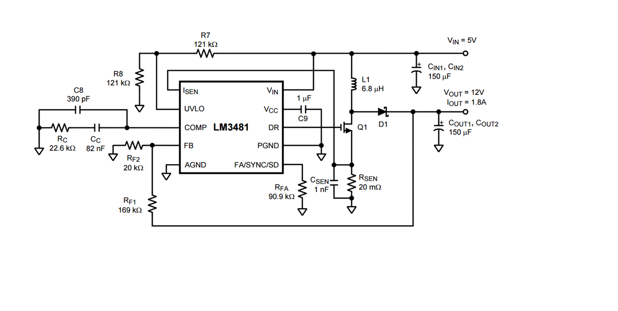
    I suggest you use LM3481,  this is a  boost controller, need external MOSFET and recfier diode. Please check the folloiwng schematic. But this part is not belong to our product line.

  • What kind of lithium-ion battery are you using that can supply 20 A current?  At this point perhaps it would be best if you can describe your application in detail.

  • Hi All,

    Still Waiting for response regarding my requirement .

    Please do not bother about battery. We have batter  that rated and we can use as per our requirement .

    So please suggest me device -

    Input - 3-4.2Vdc

    output- 5V@10A.

    Please suggest me devices as its very urgent .

    You should bother about about power source. We have that.

    as i already device we have to drive 50W motor . 

    Hope to hear you soon ...!!!

  • As posted previously, you will need switch current of close to 20 A. Can you look at LM3481 as suggested above?
  • Yes, but i din understand .
    how its function
    could you explain me basics of this so that i can understand better.
    If you have a look of this. its also have a switch current of 10A then how will it deliver 10A load current .
    Thanks.....!!!
  • It does not have EN pin as well. so it will be very difficult to keep it shut down mode as well !!!