This thread has been locked.

If you have a related question, please click the "Ask a related question" button in the top right corner. The newly created question will be automatically linked to this question.

UCD9090 Power Down sequence Implementation Issues

Hi,

Here are the Power rail monitoring and corresponding GPO Enable for the regulators.

Pin Name Pin# Monitoring Voltage
MON1 1 +5v
MON2 2 +1.8v
MON3 38 +3.3V
MON4 39 +2.5V
MON5 40 +1.8VD
MON6 41 +1.0V
MON7 42 +1.35V
MON8 45 VTT
MON9 46 S1VDD
MON10 48 +1.5V
MON11 37 +3.3VD

Pin Name Pin# Net Name Enabling Voltage Rails Power On Seq Power Off Seq
GPIO1 4 P_ENABLE1 +1.8v +2.5V +3.3V 1st  1st
GPIO2 5 P_ENABLE2 +1.0V     2nd  2nd 
GPIO3 6 P_ENABLE3 +1.5V S1VDD  
GPIO4 7 P_ENABLE4 VTT +1.35V   3rd  1st
GPIO5 10 P_ENABLE5 +1.8VD +2.5VD   4th 
GPIO6 11 P_ENABLE6 +3.3VD     5th 

1. We Implemented the power on sequence as per the above order, through Auto Enable Option. We are not finding any way to implement the power down sequence.

2. We have one GPO configured in UCD , which will send out a high when all power rails are good. This acts as as Power Up reset signal goes to CPLD. After CPLD receives this it will send out reset signals to different devices in order to bring them  out of reset. 

3. After CPLD programming is over, CPLD will send out a signal to UCD (GPI) to initiate the power cycle. This will decide the power down sequence.

 I could see other threats which raised similar issues. Give some insight how to implement this Power on & Off sequence.

Regards,

Felix.

  • Auto Enable means the UCD90xxx device will automatically sequence on rails once the device is powered up. It is not controlled by CONTROL pin or OPERATION command, so you cannot use CONTROL pin or OPERATION command to sequence off rails.

    One way to sequence off rails is to select CONTROL Pin or OPERATION command in On/Off Config setting, instead of using Auto Enable (or None). Then you will need to assert CONTROL pin or send OPERATION command to sequence on rails, and likewise, de-assert CONTROL pin or send OPERATION command to sequence off rails. CONTROL Pin is a special logic IO pin as part of PMBus port. OPERATION command is a PMBus command. In Fusion Digital Power Designer GUI, you can toggle CONTROL pin state or send OPERATION command inside the Monitor page.

    Another way to sequence off rails is through Pin Selected States feature. You can define up to 3 GPI pins to toggle among up to 8 rail states. In each state, you can program certain rails to be on and certain rails to be off. For the simplest case, you can have 2 states, toggled by 1 GPI pin. In State 0, all rails are off; and in State 1, all rails are on. During the transition of two states, the rails that are going to change on/off state will following their respective delay and dependency settings in sequenced manner. The Pin Selected States can be configured through Fusion GUI. Note that, to use Pin Selected States feature, On/Off Config setting must be OPERATION Only or Both CONTROL Pin and OPERATION.
  • Hi Zhiyuan Hu,

    Thanks for the reply.

    We are working on to CONTROL pin in order to implement Power ON/OFF sequence.

    We are trying to implement two scenarios 

    1. We are making an UCD internal logic with Power good, OV, UV and GPI intputs. We configured one of the UCD GPIOs as GPO and will carry the outcome(either HIGH/LOW) of the implemented logic. We are trying to connect this GPO to the CONTROL pin to initiate the Power ON/OFF based on its state change. Control pin has a default Pull up resistor powered with a separate 3.3V supply with which the UCD is powered up(which wont be sensed by the UCD), so that it will allow the UCD to be ready while board gets power. In this case we are considering the GPO as Open drain.

    2. We are planning to send the GPO logic output to a CPLD and based on this state CPLD will toggle another output, that will drive the CONTROL pin.

    Kindly validate whether the 1st implementation will work fine. Because, when we implement this, we are seeing the UCD is not coming up. Its not giving out enable signals and thus none of the regulators are turned on.  Whether the 2nd would be the right way to implement?

    Regards,

    Felix. 

  • Hi Felix,

    The 1st method will not work. The GPO will pull down when the rail is not Power Good (including the scenario that the rail is not started), and the GPO will pull down CONTROL to prevent it from starting. The CONTROL pin signal needs to from CPLD, and that pin must not pull down CONTROL pin before CPLD programming is finished.

    Regards,
    Zhiyuan
  • Thanks for your valuable input.

    this is the continuation of the above discussion.

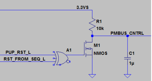
    Instead of driving the Control Pin signal from CPLD, we are trying to form the attached logic externally. At present CPLD(3.3V) and UCD(3.3VS) are powered from two different 3.3V supply.

     T

    PUP_RST_L is coming out of one of the GPO from UCD, formed by all Power good signal consideration. Till all the power lines are crossing its power good level PUP_RST_L will go high till then it will be of LOW.

    RST_FROM_SEQ_L is coming out of another GPO from UCD. This checks all the UV & OV signal levels. Any fault indicated then, it will go high.

    Will this implementation would be acceptable to initiate On/Off control?

    Regards,

    Felix.

    When both PUP_RST_L & RST_FROM_SEQ_L signals are low PMBUS_CNTRL pin will be pulled-up by the 10k resistor.

  • Probably won't work. The OV/UV fault status will keep set when you toggle off the CONTROL, and only be cleared when you toggle on the CONTROL, assuming these rails are controlled by CONTROL. You may try on EVM.

    If the purpose is to power cycle the rails when some rails are not power good or have OV/UV faults, you can use the re-sequence feature in fault response configuration.

    If the purpose is to use CPLD to power cycle rails, and the CPLD will lose power itself, you may consider to use System Reset function of the device. You can use a GPI (signal toggled by CPLD) to trip the System Reset output. The System Reset pin output can be routed to CONTROL. The System Reset pin can be configured in a way that when GPI is deasserted, the System Reset pin outputs a pulse. The pulse should be long enough for all rails to properly sequenced off. All GPIO pins' polarities are programmable, so you can have a GPI high-level as de-assert, and trip the System Reset pin pulse. You can try it on EVM.
  • Hi Zhiyuan,

    Thanks for your input. We still need feel the above discrete implementation works well for our uses cases, provided our below understanding on the functionality holds good.

    1. We are trying to access PMBUS_CTRL pin mainly to have option to implement Power down sequence on different cases like Power is not Good, any OV/UV fault on the rails & Power recycling after CPLD Programing is done. So, it may not be possible for us to drive the System Reset pin(GPO) to Control Pin by considering only Power good & GPI configuration that will be driven from CPLD after programming.

    2. If the OV/UV flag has been set, then what clears the flag? Clearance of Fault (or) Device Reset (or) Both (or) Control pin Toggle from LOW(OFF) to HIGH (ON) is sufficient enough.

    3. We are formed this external circuitry to implement the same logic that was planned to implement inside CPLD. This is mainly to avoid any situation that the CPLD supply(3.3V) goes off so that the PMBUS_CTRL Pin cannot be driven. Discrete implementation is being done with a separate supply (3.3VS), which was derived from board main power input without any control. Same 3.3VS is also powering the UCD. Here, how come the CPLD implementation alone can work and not the discrete implementation?

    4. These are the different logic scenarios we are foreseeing in the above implementation using the EX-OR Gate.PUP_RST_L is formed by ANDing all rail power good, driving high when logic is correct. RST_F_SEQ_L is formed by ANDing - ORed rail UV & ORed rail OV fault settings, driving high when no UV & OV fault occurs.

    S.No Scenarios P_RST_L RST_F_SEQ_L O/p ExOR PMBUS_CTRL
    1 All PWR Good. No UV/OV Fault 1 1 1 1
    2 All PWR Good. UV (or) OV Fault 1 0 0 0
    3 PWR Not Good. No Fault 0 1 0 0
    4 PWR Not Good. UV(or) OV Fault 0 0 1 1

    a. During when the rail is not started (#4), all GPIO will be low.  In that case PMBUS_CNTRL pin will see a High, allow UCD to start functioning.Is this understanding is right?If it is right, then this case will be retained till all the power rails are coming good without OV Fault. Now all powers are good and no fault (#1), control pin will see a high always.

    b. Either Power is not good (or) any Fault occurs, then Control pin will see a low and UCD shut down (#2 & #3). Do you think that the problem comes here, when the UV/OV flag has been set, some external mechanism is needed to toggle the Control pin (or) Reset the device?

    c. I have a point of view, when power is good and OV fault happen (#2), control pin will see a low and UCD will be shutting down. In this case, the PWR Good also will go low and as per above logic the Control pin will see a high, which in turn reset/re-power the device & reset the OV flag. Then the logic cycle starts. This will go until the OV fault is removed.

    4. We are not accessing the PMBUS lines in our design. So, we can not implement OPERATION option for power down, as you suggested on before comments. 

    Kindly help us to resolve the issue that we face on this power down implementation.

    Regards,

    Felix.