This thread has been locked.

If you have a related question, please click the "Ask a related question" button in the top right corner. The newly created question will be automatically linked to this question.

bq24040 improperly indicating end of charge

Other Parts Discussed in Thread: BQ24040

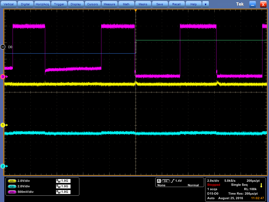
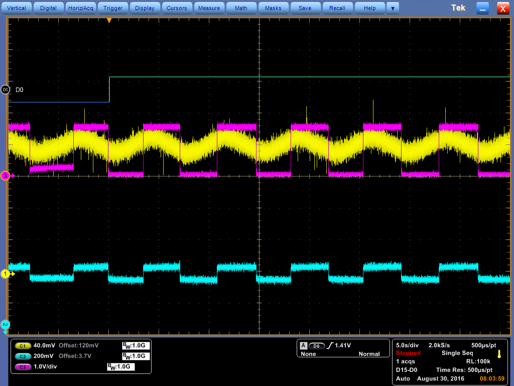
I am using a bq24040 in a single-cell Li-Ion application, and the /CHG pin is not operating as expected. Using a bench power supply, I am watching about 700 mA of current being drawn, which is slowly decreasing, but I am reading a high on the /CHG pin. I'm observing this behavior across several of my prototypes. From my interpretation of the datasheet, once plugged in, as long as the power is good, the /CHG pin should be held low until the charging current drops below my threshold, after which it stays low until reset.

I have 10k pull-ups on the /PG and /CHG pins, which then go to a microcontroller. The /CHG pins do go low when power is first applied, so it is not that the output transistors are burned out. My charge current is set to about an amp, and the PRETERM pin is floating for a charge termination current of 100 mA.

  • Can you please share your schematic along with scope capture on the issue (V_CHG, IOUT, VBAT). Have you tested on the EVM with your set up?
  • The relevant portion of the schematic is below. I don't have a current probe, so there's nothing to show in a graph. Additionally, I can't find any consistent reason for it to be acting how it is, so there's no guarantee I'd be able to catch what I'm observing on the scope. We skipped the EVM on this charger, and went right to integrating into our prototype. Other than this issue which I started noticing it's been working well enough.

  • Hi MR Flashlight  team,

    If you look at the last paragraph of the overview (section 8.1) it says that /chg will be low only during the first charge cycle after a power reset, and held at high impedance for the following charge  cycles (a small section on this at section 8.4.13). Does the issue occur in this manner, or is it constantly held high?

  • The charger will pull /chg low when the power is first applied, as expected, but /chg returns high before the charge cycle is complete. I am trying to determine if there is a particular current at which this happens, but due to the unpredictable nature of this issue I haven't gotten any information yet.
  • I realized that the ISET pin mirrored the output current, so I was able to capture the observed behavior on the scope.

    Channel 1 (yellow) is the input voltage, which is right about 5 V. Channel 2 (blue) is the output voltage, which is very close to 4.2 V. Channel 3 (magenta) is ISET, which has a gain of 1.51 V/A given that I have a 536 ohm resistor. D0 is the nCHG output.

    From this graph, it looks like the output is turning on and off due to thermal limiting. However, the nCHG output goes high even though the device is continuing to charge.

  • We  can rule out if it  is going into thermal regulation by replacing the NTC with a fixed 10k resistor. If you can, you could also add a plot to see how TS pin voltage relates to the D0 and Vout voltages.

    I also should have  asked earlier - do you have a system load in parallel?

  • The following scope capture shows the BQ24040 operating more or less normally. nCHG on D0 is held low, and it appears that the temperature TS (yellow channel) is going up and down causing the current ISET (magenta channel) to turn on and off. The blue channel is the battery voltage. Note the offsets applied to the channels.

    The next scope capture shows the point in time when the nCHG (D0) channel goes high. Even after this happens, the charging operation appears to continue exactly as before.

    During charging, my device's main outputs are off, however a number of indicator LEDs are run off of a microcontroller. There is an LED drawing approximately 20 mA max which is pulsing in and out via PWM, and a Red/Green LED drawing up to about 5 mA (not pulsing, but mixing red/green with a PWM).

  • It's almost as if it is entering TDDM (causing  nCHG to go high, but charge current still flows. A battery detect sequence  is then run), and then not detecting your battery.

    Can we:

    • verify that the battery connection is solid (it probably is, but doesn't hurt to check)
    • Measuring the DC voltage at the TS pin while this is happening.
    • Try placing a 250k resistor from TS to ground. This  will disable TDDM, and let us rule that out

  • The battery is soldered into the circuit, so there's no way it's not a solid connection.

    I placed a 250k resistor in parallel with the thermistor, and my test showed basically the same thing. I have oscilloscope captures, but they are basically the same as the prior ones so I don't think it will be useful.

    I also just ran a test with a 10k resistor replacing the thermistor altogether. It looks like that test concluded without any issues, suggesting that the problems do in fact arise from the TS functionality. Luckily, on the next revision I'm moving the thermistor onto the microcontroller so I have temperature readings during both charge and discharge. TS will have a 10k resistor and I'll be enabling and disabling by switching the output pin between high impedance and ground. If I disable the charger in this manner, and then re-enable when the temperature drops back to a safe level, will the nCHG pin be pulled down again?

    I'm still curious about what happened to cause this issue, if you have any ideas.

  • Great! I'm glad you got it worked out.

    Do you have the datasheet for the thermistor? It is not likely, but I'm curious if that was the problem. It is odd because your TS pin voltage is so low - which would indicate that the temperature is high.

    If you have a 10k pull down resistor at TS, you plan on switching the TS pin between high and GND, or the output of the charger? Or are you inserting a FET between the output terminal and the battery? I am not so sure about using the TS pin, you could probably manipulate the voltage to make it "think" it is in high temp and disable.

    If you are inserting a FET between the OUT pin and battery, it would be just like removing the battery and reinserting it, causing a fresh charge cycle (pulling nCHG low for the first charge, high for recharge cycles)
  • We were using a Murata NCP15XH103F03RC. It's B value is basically exactly the same as the parts specified in the BQ24040 datasheet. Make sure that you account for the offset applied on the oscilloscope when reading the TS voltage - there's an extra 120 mV in there, which I needed to be able to get the resolution I wanted.

    I plan on switching TS between 10k and GND. Instead of the microcontroller pin being an output driving either high or low, I'll instead be setting it as either an input, therefore high impedance, or an output driving low. I believe the datasheet indicates that it can be used this way, and even shows an example where the microcontroller can drive this pin low to disable the charger. It just leaves the question of what happens when the charger is disabled by pulling TS to GND, and then re-enabled by releasing it again.

    The FET is not a bad idea, but I have about 4 square centimeters of board space to work with, at least half of which is already claimed by connectors and a switch. I don't have the room to be throwing extra components in when it seems like it can be avoided.
  • You are correct - no need to take up board space if you can help it. I looked at the plot in the datasheet that I think you are referencing. The charger should treat that as a new charge cycle (it also says this in section 8.3.4), so it will be the same as if you removed the battery or power source.