This thread has been locked.

If you have a related question, please click the "Ask a related question" button in the top right corner. The newly created question will be automatically linked to this question.

TPS61027 weird behavior for charged/discharged battery

Other Parts Discussed in Thread: TPS61027, TPS61020, TPS61252, TPS61230

Hi all,

I'm having issues with the output voltage of a fixed voltage boost converter (TPS61027 - 5V). Our design is similar to the one on Figure 25 of the datasheet, except we do not use LBI and LBO (LBI is connected to VBAT and LBO is left floating) and EN comes from a microcontroller. This circuit is powered by a single cell lithium ion battery.

When I measure VOUT right after we enable the circuit I get different values if I have a (somewhat) full battery and if I have a "less full" battery. With a 4.05V battery I measured 3.3~3.4V at VOUT immediately after I enabled the circuit. With a 3.7V battery I got ~5.12V. I initially thought that it was not working, but as I monitored the output I realized after some time VOUT would finally go to the desired 5V.

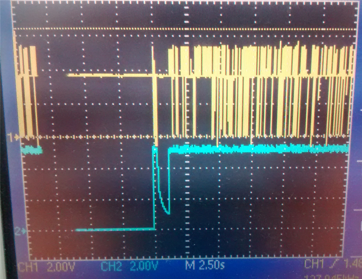
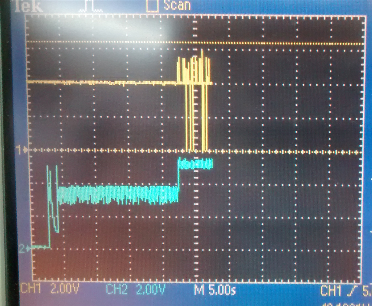
Looking at VOUT and SW with an oscilloscope, I can see that the output gets to 5V when the circuit starts switching (about 18 seconds after enabling it) (I attached 2 images of the 2 different situations). The first drop is related to the connection of the load. (Yellow signal is SW and blue is VOUT).

Is there any know issue about this behavior? Could this be a result of the power saving mode?

  • I just tested it connecting the PS pin to VBAT and got the same results, so I guess it is not related to power saving mode...
    (I also just reread my post and, to clarify things, the first image is the "low battery" situation (3.7V) and the second one the "full battery" (4.05V))
  • I guess the problem is that the load is connected before the TPS61027 finish the startup. refer to the application note "TPS61020 Boost Converter Start-Up and Precharge" for more detail. please try to delay the load connection.

    sometimes, this kind of abnormal behavior is caused by the bad layout. could you share your schematic and layout?
  • I tried to delay the load connection and got the same results, only seconds later. Reading the application note I can assume you think the TPS61027 would be stuck in start-up mode?

    The thing that bothers me the most is the fact that in every application note/datasheet the prediction is that it would have abnormal behaviour in situations where the battery is run out, not the opposite - which is my case. Do you have an email I can send the schematic/layout to?

    att.

    Diogo Furukawa

  • yes. could you measure the inductor current during the abnormal period? i guess the load startup to operate at 4V and absorb high current. while in low battery, the load doesn't work. my email: jasper-li@ti.com

    by the way, why do you select TPS61027? There are better device for your application, such as TPS61252, TPS61230.
  • Hi Jasper,

    just to update the issue, I think I found my problem. I was using a 47uF tantalum capacitor at the output with ESR of 2ohm. The datasheet doesn't specify a range of ESR, but I found this post where someone says something between 100-300 mOhm would do (e2e.ti.com/support/power_management/non-isolated_dcdc/f/196/p/178899/645000).

    I don't have a tantalum cap here within the specs, but the datasheet does say I could use a ceramic cap with a resistor in series, so I did that (roughly 47uF and a 0.1 ohm resistor) and it works like a charm. I found a capacitor that would fit my project (TPSB476K010R0250), it is rated for 47uF and 250mOhm, do you think this would be fine?

    att.

    Diogo Furukawa

  • the tantalum should be OK. it would be better if you can find a approximate 100mOHM ESR cap to reduce the output ripple. please try it in the current board to double check if the problem is solve.

  • The 250mOhm tantalum 47uF cap just arrived here, and it works just fine.

    thanks for the help!