Hi
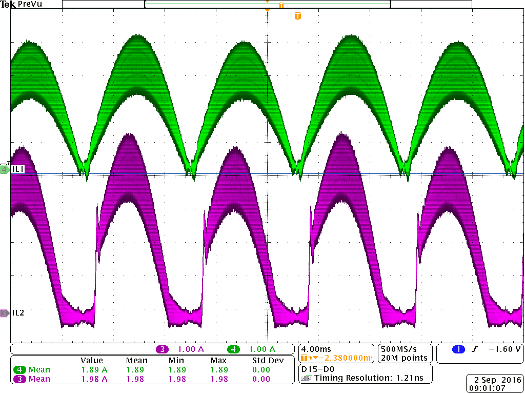
I've designed a 1.2kW PFC universal input 400 V output with UCC28070. When I apply 100rms input to the prototype the voltage look regulated but the problem is in inductor current of phase 1. This is an interleaved topology and 2 phases are exactly identical; Same inductor, same Mosfet , current controllers and sensors (CT) and other parts all the same. But the indcutor current for phase 1 is different from 2 in a bad way. I have uploaded the picture here. Inductor 2 look very good but indcutor current 1 looks distorted with more distortion at zero crossing. I know the reason for zero crossing issue is negative current and very low input and very light power and I checked the inductor current for phase one and it is indeed negative around zero crossing area but inductor in phase 2 doesn't have any negative current in the same area. And I know I can add the proposed dc offset circuit in UCC28070 datasheet to solve the issue. But why my other phase doesn't have these issues? Other than the zero crossing issue there a overshoot in current of L1 as can be seen in picture.I was able to smooth this overshoot by changing current controller but not the zero crossing issue.. The question is why I don not have this problem in phase 2 that has exactly the same current loop controller? I even swap the inductors in phase 1 and 2 and it did not help.
Thanks


