This thread has been locked.

If you have a related question, please click the "Ask a related question" button in the top right corner. The newly created question will be automatically linked to this question.

TPS65910 can't generate VREF

Other Parts Discussed in Thread: AM3356, TPS65910

  Hi, I have a problem about PMIC TPS65910A3.

I copied the ICE BOARD(tmdxice3359) circuit and made board with AM3356.

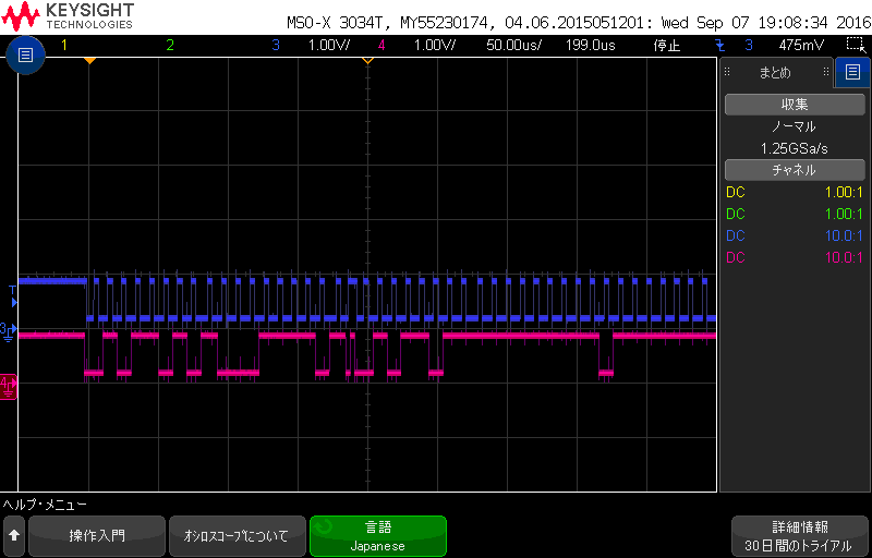
While start-up, TPS65910 sequence stops on the way, as below.

1. VCC7 = 5.0V provided. -> OK.

    (PWRON rises 0V to 5.0V via internal PullUp.)

2.VRTC = 1.8V oputputted. -> OK.

3.AM3356 set PWRHOLD 0V to 1.8V ->OK.    (So far, this is same sequence as ICE BOARD.)

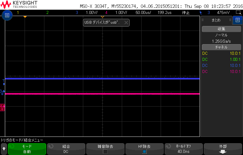
4.VREF remains 0V. No other powers start up. (ICE BOARD can generate VREF, however my trial board can't.)

Then I tried PWRON tied to GND, but same result.

(According to DataSheet P.46, the statemachine shows PWRON=L masks other signals.)

EEPROM has not chenged yet.

If you have any information about this issue, please let me know any solution.

Thank you.

  • Hi user4667465,

    Today is US Holiday. Thank you for your patience and our experts will provide feedback tomorrow.
  • Do you see any activity on VREF when you short PWRON to GND?

  • Hi,Richard-san.

    Thank you for your prompt response.

    I confirmed the VREF while PWRON tied to GND.
    Unfortunately, VREF remains 0V.(as described above thred)

    Now I try to read internal EEPROM register via I2C.
    It may show any clue.
  •  I tried to read internal EEPROM register, but failed.

    I used USB-I2C converter as below.

    akizukidenshi.com/.../Adafruit_FT232H_Breakout.pdf

    I  connected PMIC's SCL and SDA to exernal power supply(ePS) via 3kohm.

    After PMIC power-on and ePS set to 3.3V, SCL and SDA droped to 0.9V.

    When ePS raised to 5V, SCL & SDA remained 0.9V.

    (I suppose PMIC I2C lines are protected by Zennner Diode to prevent Over Voltage malfunction.

     Maybe PMIC start up properly, then Zennner Diode is cut off from I2C lines....)

    (CH3 = SCL, CH4 = SDA)

    When I sent "Read Command" under the situation(from converter to PMIC), I2C swang 0.9V-0V.

    But the voltage was too low to recognize the serial packet for converter and PMIC.

     Probably, my PMIC sequence can't reach the I2C available step.


     If there are any checking contents for me, let me know anything.

    Best Reagards.

  • Can you confirm VREF does not have a short to GND?
    Is the power-pad properly soldered to GND?
  • Were you able to confirm there were no shorts on the board and the power-pad was properly soldered?

    I didn't see any errors in the schematic you sent over, and I'm not sure why the i2c lines would be 0.9V.

    Does removing the TPS65910's i2c pull-ups resolve the 0.9V condition?

  • Hi, Richard-san.

    Thank you for your advice.

    >Were you able to confirm there were no shorts on the board and the power-pad was properly soldered?

    Yes, I confirmed the resintence between VREF and GND.

    As a result, it was Mega ohm detected. And 0.01uF was also.

    (It identificates circuit diagram.)

    I can't cinfirm power-pad soleder condition,but I checked no wrong short to GND at PMIC pins.


    >Does removing the TPS65910's i2c pull-ups resolve the 0.9V condition?

    Yes, I tried to check I2C communication as below.Would you look into the diagram?

    I2C connectin diagram.pdf

    Thank you.

  • For assurance can we isolate the TPS65910 from other i2c devices on that bus, by removing R69 and R72 then re-confirming the 0.9V?

  • Hi,Richard-san.

    Thank you for your response.

    I improved the low-voltage problem (rose from 0.9V to 3.3V as attached below).

    The reason was that I didn't supply PMIC's VDDIO, so I supplied 3.3V to VDDIO.

    (Of course R69 and R72 were removed.)

    But, PMIC returned no ACK via I2C.

    According to SLVA704, my command from Master port seems to be correct.

    (When I didn't supply any power to PMIC and Master sent same command to PMIC, I2C waveform was same as power supplied.)

    slva704.pdf

    PMIC power was supplied.

    I2C_READ.pdf

    PMIC power not supplied.

  • Did VREF recover to 0.8V? If not, the PMIC is probably still OFF and would not have i2c capability.

    Can you confirm the full part number on the populated board?

    In case of ESD damage, does replacing the PMIC fix the issue?
  • Hi,Richard san.

    I appreciate your constant response.

    Today, I tried rmoving R288 and BOOT1 became internal Pull Down.

    Then, PMIC generate VREF to 0.9V.

    Under the condition, VDA=2.2V,VPLL=1.8V,VAUX1=3.0V,VAUX2=3.0V,VFB1=1.1V,VFB2=2.8V,VFBIO=1.8V,VDIG2=1.1V,VAUX33=0V,VMMC=3.3V.

    Though they aren't my desirable voltage, PMIC appeared any change of starting condition.

    I have two question.

    Are there any difference between BOOT=00 and 11 during start-up?

    When PMIC generate strange voltage different from default setting?

    If possible, would you escalate this problem in your company?

    Thank you, best regards.

  • Each TPS65910x only has 3 boot modes, 00, 01, and 10, where 11 is not defined.
    Setting the BOOT1 = 0 configures your PMIC for 00 boot mode, defined in section 5.22.1.1 of the datasheet, which will change the output voltages and the sequence that they are enabled.

    Even still, your VDAC, VDD2, and VAUX2 voltages are not what I would expect, so I would check for any possible paths to other supplies.

    The reason I asked for confirmation of the part number is that each TPS65910x device is configured differently for BOOT0=0 and BOOT1=1. The behavior you're seeing would make sense fora different device that expects an external crystal, which might ignore PWRHOLD until there was a valid clock.

    Can you confirm that you have a TPS65910A3 or TPS65910A31 on the board?
  • Hi, Richard-san.

    Finally, I could start up normally.

    I'm sorry that I mistook the part numer which is TPS659101 instead of TS65910A3.

    I replaced new IC and the borad generated correctly (of course VREF also).

    I appologyze my easy miss and appreciate your sincerly support.

    Thank you.