This thread has been locked.

If you have a related question, please click the "Ask a related question" button in the top right corner. The newly created question will be automatically linked to this question.

Flybuck or buck + transformer driver, smaller and most efficient solution

Other Parts Discussed in Thread: LM25018, LM5161, LM5160, TPS82130, SN6501, LM5017, ADS131E04, LM25017, PMP15006, TPS7A87

Hello,

I have to build a power system with a 12 V nominal input (range about 10-14 V) and 3 output lines:

1. 3.3 V, 120 mA max

2. isolated 3.3 V, 15 mA max

3. isolated 5 V, 15 mA max

Lines 2 and 3 have to be powered by LDOs as they need to be not much noisy. By scaling them with voltage and with a supposed 80% efficiency, what I need is a 6-7 V, 130 mA line which has to be connected to the first 3.3 line and with an isolation barrier in the middle. Obviously, this means that the 3.3 line current output raises to about 250 mA.

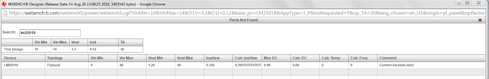
I tried to give a look at Webench, but it only gives me fly-buck options with LM5160 and LM5161 with huge transformers. Looking around, I found LM25018 to be more suitable for my application, but don't understand why Webench did not suggest it. Moreover, when I try to start a design in Webench directly from its page I always have an error "The server is temporary unavailable". Hence the question: did I miss something? Is there a practical reason which suggests me not to use it?

My alternative is buck converter (TPS82130) plus transformer driver (SN6501). This uses two parts, but is maybe easier to design, because the transformer does not have to match the inductor requirement of the primary output of the fly-buck converter.

I need the board to be as small as possible, so footprint is the first parameter to look at; efficiency is the next one, while BOM cost is not SO important this time.

Which of the two alternatives do you suggest? Why? Is there a third way?

I also add another information and another question: on the board I have two clocks at 2.048 MHz and 5 MHz (this one is an SPI clock, so it is not always on). which frequency should I choose for the buck converter in order to minimize interference?

Thanks in advance for your help.

Stefano

  • Hello Stefano,

    The way I look at your application from the Fly-Buck topology point of view, you have a primary non isolated output voltage (Vpri: 3v3@120mA) with two isolated secondary outputs set at ( Vsec1: 3v3@15mA and Vsec2: 5V0@15mA). Based on these details, you would need a triple winding Tx/coupled inductor with the turns ratio set as Npri:Nsec1:Nsec2 = 1: 1.2: 1.667. These turns ratios are calculated taking into account the secondary diode drops and the leakage inductance of the Tx, hence the slight over design in the turns ratio. Your effective primary load (taking into account your primary and secondary loading would be close to 163mA (Ipri +Nsec1/Npri * Isec1 + Nsec2/Npri *Isec2).

    The reason the Webench shows higher values of the Lpri of the Tx is due to the light effective primary loading (and ~30% inductor current ripple assumption). Although the values calculated may be correct, you can go low much lower Lpri Tx values since the Fly-Buck topology is purely a sync Buck topology (can handle negative current) and check for 100% or higher inductor current ripple assumption if needed). This should help you bring the Lpri value down.

    Another reason why the Webench is unable to get you a design is due to the dual secondary winding requirements in your application. At present, the Webench tool (for the LM5017, LM5160 and the LM5161) is only equipped for a single isolated winding application.I agree for the given application you have, the LM25018 can be better fit as it can handle the light load requirement and can will get you better efficiency numbers compared to the LM5160 (or LM5161) due the much lower Iq current value.

    Please shoot me an email with more details of this application and I can send you a schematic design about what I am talking about here.

    Regards,
    Sourav
  • Hi Sourav,

    as I wrote in my first post, lines 2 and 3 have to be powered by LDOs and not directly by the fly-buck converter, as they need to be noise free (this is especially true for the 5 V line, which has to power an analog sensor and an ADS131E04). This leads to two lines: a primary 3.3 V, 120 mA line, and a secondary 6 V, 130 mA line. With this schematic in mind, I tried to use Webench but had no success.

    By the way, what about the alternative solution with two separate ICs?

    Thanks.

    Regards,

    Stefano

  • Hi Sourav,
    can you please reply to my previous post?

    Thanks.

    Regards,
    Stefano
  • Hello Stefano,


    Regret the late reply. Sorry for the confusion. Now I see what the issue might me with the LM25018 WEBENCH design.

    If you are planning to use say 6.6V(@130mA) for the isolated secondary output and the primary voltage at 3.3V (@ 120mA) you will need a Tx with effective turns ratio as 1:2 (Npri:Nsec). In that case your effective net primary current will be (120mA+ 2 x 130mA). Then your net primary current will close to 380mA. While calculating the primary inductance of the Tx, one needs to calculate the Lpri ripple current which is generally set at 30% of the net primary current.

    If 380mA is your net DC primary current and you have a ripple of say even 30%, your peak Lpri current will more than 390mA (the minimum peak current limit of the part) and the IC will exceed the HS FET current limit. At least that is the case for the LM25018.

    However, that being said, the L25017 should have shown in the Webench. I will need to follow up with Webench team for this issue.

    I suggest you use the LM25017 for this design followed by the LDO for the secondary outputs. I will not be the correct apps person to advice about the TPS part as I do not support that part. However, I think it should be doable, but you will lose the scope to change your secondary output range, if the need arises.

    Regards,

    Sourav

  • Hi Sourav,

    according to the math, the secondary should be a single 130 mA 6.6 V line. From this line I can take enough current to feed the two LDOs (5 V @15 mA, 3.3 V @15 mA). However, Webench did not work even if I reduced both primary and secondary currents, so I suspect the problem could not be the minimum peak current limit.

    By the way, my original doubt was about the choice between the two possible topologies: LM2501x or TPS82130 and SN6501; which one can give me the minimum board space and maximum efficiency?

    Thanks again.

    Regards,

    Stefano

  • Hello Stefano,

    I repeated the same range again in the Webench and I got the same issue again (exceeds current limit). See attached.

    I used 10-14 as VIN, 3.3V@120mA as VOUT1 and 6.6V@130mA as VOUT2. Checked the isolated output option. Of course it just shows up the LM5160 and the LM5161 as results but if click on 'show why other parts were not found' you should be able to filter out the LM25018 and see the reason.

    That said, a Fly-Buck approach will be very space-conscious and will need only one Tx, a diode and the preload resistors. There is no need for any snubber circuit and with less stress on the SW node.

    I have attached here a custom schematic (with 1:1.5 Tx) where we had created a design for one customer using the LM25018. You can see the component count here and you should be able to keep the board size to 15mm x15 mm (or lesser: see PMP15006). You should be able to secure an efficiency of more than 82% with this design.

    Regards,

    Sourav Ref_Schematic.pdf

  • Hi Sourav,

    I used the same parameters and got the same result. This is good news, I guess... ;) but does not solve my issue. I will work on your schematic suggestion, which, I think, can solve my problem. By the way, I'm not able to find the transformer (75031629): can you give an advice about manufacturer or supplier?

    Thanks.

    Regards,

    Stefano

  • Hello Stefano,

    It is 750316229. This Tx was designed by Wurth for one of our specific customer applications (very similar to your requirements). I do not think it has been realeased over the web. However if you want to contact them and ask for samples they should be able to send you a few, depending on the turns ratio.

    One important thing to note is that in Fly-Buck application, one needs to strive for really tight leakage inductance numbers (1% or less preferably) for the Tx, as it impacts the secondary side output voltage. However in your case, you need not worry about it too much since you are going to post regulate it.

    Regards,

    Sourav

  • Hello Sourav,
    you are right, that transformer cannot be found on the web. But, thinking more about it, I need a different turns ratio, because my primary output is 3.3 V and secondary output should be between 6 and 6.5 V, because I have a TPS7A87 (dual LDO), whose maximum input is 6.5 V, and I should take into account the diode drop even at 0 A in order not to violate the input voltage range.
    That said, I think I need a turns ratio of 1:1.8 or 1:1.9, but I am not able to find a suitable part. I used equations 25 and 26 of LM25018 data sheet in order to find the L value. I used:
    Iout1 = 120 mA
    Iout2 = 30 mA
    N = 1.9
    f = 0.957 MHz (with a Ron of 38.3 kohm)
    Vin_max = 15 V
    Vout = 6.3 V
    With these values I got 8.96 uH for L, so I think I could use a 22uH part.

    Can you please help in finding a suitable transformer? I'm looking at many manufacturers' portfolios, but I'm not able to find anything which matches my needs... what else could I try?

    Thanks again.

    Regards,
    Stefano
  • Hi Sourav,
    I am going on in my search for a suitable transformer, and found this part: Coilcraft LPR4012-223BM (22 uH, 1:2, k = 0.95, 0.43 A Isat); it's a coupled inductor, but should solve, I think.
    It seems to me that a little problem could be the high DCR (1.16 on L1 and 3.65 on L2 max). Moreover, the slightly high turns ratio (1:2) forces me to lower the primary output voltage to 3.15 V in order to have room for the output to be < 6.5 V even when I take into account all tolerances.
    Do you think this solution could be ok for me?

    Thanks.

    Regards,
    Stefano