This thread has been locked.

If you have a related question, please click the "Ask a related question" button in the top right corner. The newly created question will be automatically linked to this question.

BQ40Z50-R1 takes too long to go into fast charge

Other Parts Discussed in Thread: BQ40Z50-R1, BQSTUDIO

We have some question regarding the BQ40Z50-R1. 


1. We set the CUV, CUVC and Shutdown threshold at 2875mV, 2775mV and 2675mV. Then we DSG the battery until the CUV trip. Then we DSG it further until around 2400mV (shutdown voltage also trip). After this we connect the battery into a charger. The charger Iprecharge is set at 200mA. While it is connected to a charger, the BQStudio would only detect ~10mA of charging current not the 200mA Iprecharge. Why would it only charge using 10 mA not the 200mA?


2. How would one charge a battery after the CUV trips (XDSG=1, DSG=0)? At this scenario we would like to charge using a precharge current then after the battery voltage goes beyond a certain voltage we then switch to a fast charge current. In our testing though, since the CUV disable the DSG FET, the charge voltage is not even seen by the battery. What we observe in this case is PCHG FET is enabled, DSG FET is disabled then only small amount of charge current is passing.


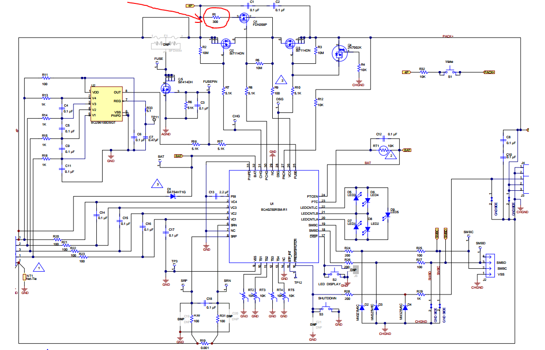
Our fuel gauge schematic is the same as that in the typical application so there should be no issue there.

What we're seeing with the 10mA charge is that it takes way too long to go into fast charge. We don't even see the precharge current of 200mA as it goes from 10mA to full charge current (1.5A). Also at 10mA, the charge LED does not come on so the user will be wondering what's going on.

Please help with this.

  • Hello Mehdi,

    Can you please provide the your g.csv and .srec files from your gauge, exported from bqStudio? How many series cells you're using?

  • Hi Damian,

    Please see the attached. Using 2S1P configuration.BQ40Z50-R1.zip

  • Hello Medhi,

    Is your charger setup to provide 200mA of charging current from  2.5V to 2.9V? The settings in the gauge should match your battery charging specs and your charger charging profile. The gauge can't control the current to 200mA during pre-charge phase. It's a threshold and if the charge current exceeds the 200mA  set for pre-charge the gauge will disable the pre-charge FET and enable it when the current drops below the set level. The 10mA the gaugeis reporting is an average current from PCHG FET enabling and disabling. Therefore it take a while to charge cells to 2.9V. When the cell voltage reaches 2.9V the CHG FET is enabled and the threshold is 1.98A. The charger current is ~1.5A, which is the below the threshold and not enough to trip the protection as in the pre-charge phase.

    DSG and CHG is based on the direction of the current. The gauge disable current flowing (negative) from the battery, but allows current following into the battery (positive) for charging after the CUV trips (XDSG=1, DSG=0).

    As for the charge LED, if you resolve the pre-charge issue mentioned above the LED will be ON long enough to be visible to the eyes.

  • Hi Damian,

    In the gauge setting, we set the pre charge current threshold to be 227mA (2.5V to 2.9V) then fast charge @1.98A or more (depending on Low, Med, High voltage range). The charger on the other hand is set to precharge at 200mA at up to 3.1V and then fast charge at ~1.5A. With this setting the charger current will always be lower than the threshold set by the gauge so it should not trip either the CHG FET or the PCHG FET. What we are seeing is after the CUV trips (XDSG=1, DSG=0), the PCHG will be always enabled (bases on Operation Status A) but for some reason the current is stuck at 10mA. I see what are you saying by the DSG and CHG is directional. It is because of the body diode of the FET is still letting current to flow on the opposite direction. But for some reason the current is being stopped somewhere to be 10 mA. Where did you see that the PCHG FET keep toggling? Is this from the charge log that I provided?

    Thanks.
  • Hi Mehdi,

    Let me correct my previous statement about precharge. The precharge current set in bq40z50-R1 isn't a limit rather a broadcast from the gauge to the charger on current to provide. During precharge stage the CHGFET is turned OFF and the PCHGFET  is turned ON. The precharge current can be limited by bq40z50-R1 by putting resistor in series with PCHGFET. In the case of our EVM this resistor is 300-ohms.  In this case the precharge current will be (Charger voltage - BAT pin Voltage)/300-ohms.

    I would recommend reducing the series PCHGFET resistor value. Assuming your Charger voltage is 8400mV and BAT pin voltage is 4800mV based on your log file. If there's 300-ohms resistor in series with PCHGFET then the  precharge current is (8400mV-4800mV)/300-ohms => 12mA. To achieve 200mA precharge current the series resistor needs to be <18-ohms for the same charger voltage.