This thread has been locked.

If you have a related question, please click the "Ask a related question" button in the top right corner. The newly created question will be automatically linked to this question.

BQ40Z60 - 7.4V 2S Battery - Learning Cycle Failure

Other Parts Discussed in Thread: BQSTUDIO, BQ40Z60

Dear,

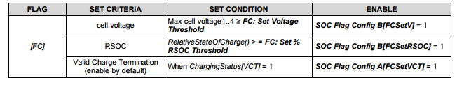
I have been working on getting the BQ40Z60EVM to correctly gauge my 2S LiPo battery (250 mAh) for an entire week straight, but no progress. Most likely because I somehow cannot complete a full learning cycle. This due to not being able to charge to full charge giving [FC] = 1. At the bottom I've added a gg.csv file. Could someone please give me some guidance, or provide a modified gg.csv file I could work with?

Extra related questions:
- My adapter delivers 12V/5A to the EVM and the Charging Voltage is a nice 8400mV but the AC adapter voltage reading in bqstudio is only around 7950mV. Shouldn't this be the same as the Charging Voltage and how do I fix this?
- The Technical Reference Manual (TRM) gives default values for the charging voltage at different temperatures. Why would this voltage be lower for the recommended temperature as opposed to the standard temperature?
- Where did the GaugingStatus Low Word go? There is a description of it in the TRM (with a very weird RDIS interpretation!), but in the BQ40Z60, it's not there.
- The Charge Termination Current & Voltage is per default 100mA & 75mV. Where do these numbers come from and how can I calculate them for my situation? 

General questions:
- Where is the [TCASETVCT] flag located mentioned on p. 63 of the TRM?
- In Settings:Configuration[FET Options] bit5: CHGFET. This is mentioned in the TRM as RSVD. What do I do with this bit?
- Regarding system presence: shunt on J7, [NR]=0 gives [PRES]=1. If battery pack removed nothing changes, only when shunt is removed from J7, [PRES] toggles regardless of battery pack installed. This seems not correct.
- With charger and load connected, [FET_EN]=0, [CHGR_EN]=0 but no battery connected, the voltage reading is still around 40mV for cell 1. How is this possible?
- The TRM mentions on p.23 that the value for Protections:CHGC:Recovery should be negative. (As well as for Protections:PCHGC:Recovery on p.24). But both default Recovery Thresholds are positive. Why?
- What does Settings:AFE do? The TRM does only mention default values and not much explanation.
- To be sure: are protection values like CUV/COV and charging voltages in the advanced charging algorithm section given per cell or by battery pack?

I am truly sorry for this many questions. If I'm able to run a learning cycle I will already be very happy and all the rest is an added bonus. Many thanks in advance for any responses.

Floris Rouwen

6sept2016.zip

  • Hi Floris,

    I will review your post and gg file and respond tomorrow.

  • Hello Floris,

    What ChemID are you using for your battery? I would recommend doing a full discharge to cell discharge cut-off voltage, full charge to cell charge cut-off voltage and full discharge to cell discharge cut-off voltage with logging turned on in bqStudio. Once you've completed the charge and discharge cycles. Use our GPC to find the best chemID match for your cell. Update the gauge with the recommended chemID using bqStudio then run your learning cycle.

    I will respond to your other questions later today.

  • Hello Floris,

    Here's my response to your questions:

    Extra related questions:
    - My adapter delivers 12V/5A to the EVM and the Charging Voltage is a nice 8400mV but the AC adapter voltage reading in bqstudio is only around 7950mV. Shouldn't this be the same as the Charging Voltage and how do I fix this? 

    [Damian] the charger voltage is measured at the ACP pin. There's is a voltage drop across the series 10k resistor, which is due to some current draw by the charge pump powered from ACP pin and used to drive the ACFET. There's no need to fix it or change AC adapter. It should be still above the cells charge cut-off voltage.


    - The Technical Reference Manual (TRM) gives default values for the charging voltage at different temperatures. Why would this voltage be lower for therecommended temperature as opposed to the standard temperature?
    - Where did the GaugingStatus Low Word go? There is a description of it in the TRM (with a very weird RDIS interpretation!), but in the BQ40Z60, it's not there.
    - The Charge Termination Current & Voltage is per default 100mA & 75mV. Where do these numbers come from and how can I calculate them for my situation? 

    [Damian] Charge Termination Voltage is how much over the cell max voltage to terminate charging. Charge Termination Taper Current is new charge current value once the charge termination occurs.

    General questions:
    - Where is the [TCASETVCT] flag located mentioned on p. 63 of the TRM? [Damian] It's in the SOC Flag Configuration A register located in bqStudio at Data Memory tab>>Settings>>SOC Flag Configuration A.

    - In Settings:Configuration[FET Options] bit5: CHGFET. This is mentioned in the TRM as RSVD. What do I do with this bit? [Damian] This is an error in the TRM. When FET Options[CHGFET] = 1 disables CHGFET at valid charge termination.

    - Regarding system presence: shunt on J7, [NR]=0 gives [PRES]=1. If battery pack removed nothing changes, only when shunt is removed from J7, [PRES] toggles regardless of battery pack installed. This seems not correct. [Damian] most equipment and battery packs have a pin to check if the system is present. When the pack is connected to the system the SYSPRES pin is pulled low, When the pack is removed the SYSPRES pin is pulled high. If the pack/equipment doesn't have this feature. It can be disabled by setting [NR] = 1.

    - With charger and load connected, [FET_EN]=0, [CHGR_EN]=0 but no battery connected, the voltage reading is still around 40mV for cell 1. How is this possible? [Damian] This will be resolved by calibrating the gauge with bqStudio.


    - The TRM mentions on p.23 that the value for Protections:CHGC:Recovery should be negative. (As well as for Protections:PCHGC:Recovery on p.24). But both default Recovery Thresholds are positive. Why? [Damian] Charge currents are positive and discharge current are negative.


    - What does Settings:AFE do? The TRM does only mention default values and not much explanation. [Damian] I need to check on this and get back to you.


    - To be sure: are protection values like CUV/COV and charging voltages in the advanced charging algorithm section given per cell or by battery pack? [Damian] It's per cell, It's Cell Under Voltage and Cell Over Voltage.

  • Damian,

    Thanks so much for all the answers. First of all I'm using a very standard LiPo battery with also a standard ChemID. (0100 if I'm correct.)

    I'm still unable to charge the battery to more than 8100 mV while the charging voltage is set to 8400 mV. Would you happen to have a gg.csv file for a two-cell LiPo that you could send me?

    Thanks again!

    Floris

    PS. I'm still interested in the answer to this question:
    - The Technical Reference Manual (TRM) gives default values for the charging voltage at different temperatures. Why would this voltage be lower for the recommended temperature as opposed to the standard temperature?

  • Hi Floris,

    I don't have gg file for 2SP1 LiPo cells. I can check with my colleagues. I do recommend you using our GPC tool to find the best matched chemID.

    If you send me your gg file, I can take a look. Even if your charging voltage is 8400mV, you will have series resistance of the FETs and cells that would cause some voltage drop.

    The AFE protection settings is in the TRM on page 157.

    Why would this voltage be lower for the recommended temperature as opposed to the standard temperature? The cell resistance decreases with higher temp. The standard high temp is higher than recommended temp, hence resistance is lower and  the voltage is lower (less of a voltage drop across the cell series resistance)

  • Hi!

    Thanks again.

    The gg file is located at the bottom of my first post. 'sept2016.zip'

    Floris

  • Hello Floris,

    I reviewed your GG file. It looks like your EoC for the cells get to 4172mV and 4189mV, respectively; but the charge termination [TC] and full charge [FC] voltage thresholds are set to 4200mV. If the cells voltages aren't greater than or equal to the threshold voltages set, [FC] flag won't get set. You will have to increase the AC adapter voltage or reduce the thresholds to 4150mV. Also you need to make sure RSOC >/= TC set % RSOC Threshold. These settings are located Data Memory>>Gas Gauging.

    Page 64 of the TRM list the three conditions that must be met for [FC] to get set.

    Also I noticed that the Qmax Cell 1 and 2 are 125mAh, but Qmax Pack is 250mAh. What is your cell configuration? 2S2P? If it's 2S1P as previously mentioned then the pack capacity should be the same as the cell capacity, since the cells are not in parallel. Pack capacity is cell capacity x ?P and Pack voltage is cell voltage x ?S. I recommend you update the Qmax cell or pack to match and design capacity in mAh and cWh.

  • Dear Damian,

    Thanks so much for this answer. This will probably do the trick :)
    Thanks again for all the help.

    Floris