A related question is a question created from another question. When the related question is created, it will be automatically linked to the original question.
If you have a related question, please click the "Ask a related question" button in the top right corner. The newly created question will be automatically linked to this question.
It is recommended that you leave those parts in place.
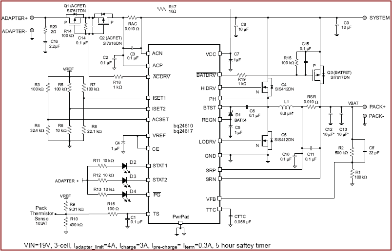
Q1, Q2, are the FETs used to prevent boostback from occuring, and having your battery powering back into your adapter.
R14, C14, and R18 are used to properly drive those FETs.
R17 is used to protect the VCC pin (it is not recommended, but you may be able to remove this. The space savings from 1 resistor will be almost negligible, though)
RAC is required by the IC, as it is used to sense the input current. The sensed current is then used in one of the control loops internal to the device.
C3 is a differential filter for the current sense traces, and C2 is a common mode filter for the traces. These are recommended, as the control loops driven by these signals are sensitive to noise.
I believe your original question was if you are able to remove the power path feature. If you have to use the bq26410, you may be able to get by with removing Q3. Depending on how the gate is driven internally, you might be able to let it the BATDRV pin float, or connect it to ground through a properly sized resister. However, I would still recommend using the bq24600 if possible. That IC is designed for no power path, and the only other major difference is that the switching frequency is 1.2MHz rather than 600k Hz,
David: Q1, Q2, are the FETs used to prevent boostback from occuring, and having your battery powering back into your adapter.
Rais: Can I remove Q2,R14 and C14 and change it to zener diode connect from Pin-G to Pin-S? If have Q1, Zener diode, R18 it can be work as reverse polarity protection right?
David: BATDRV pin float, or connect it to ground through a properly sized resister.
Rais: Thanks for your advise.
I still want to use this because this IC has feature TTC pin for safety timer and termination control.
It seems like you are really trying to use the absolute minimum. If you really have to, I suppose you would actually be able to do away with Q1, Q2, R14, C14, and R18 and just place a schottky diode between the adapter and ACP. The device will still function, but you will not have the ACDRV logic the device offers. If you float ACDRV and BATDRV, it should be okay.