This thread has been locked.

If you have a related question, please click the "Ask a related question" button in the top right corner. The newly created question will be automatically linked to this question.

LMR14020: Design Review

Genius 5355 points
Other Parts Discussed in Thread: LMR14020

Hi Support,

The problem with this part is we did some calculation and found the power dissipation for the LMR14020 DCDC is not a lot.

Temperature rise at most limited to 2degC.

However, when we tested the actual part, there’s excessive heat dissipation and a 10degC rise in temperature in the observation.

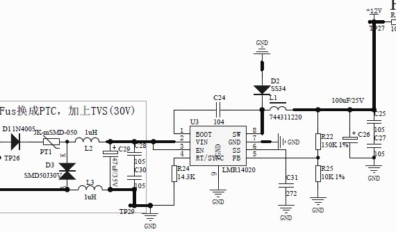
 Are you able to help review the design?

Based on +16V maximum input and iout of 0.42A, the P-pk ripple current is about 0.34A and the iRMS is 0.18A.

The heat dissipated across RDSon is not much.

So we are not sure why there is a 10degC increase in temp.

Thanks.

  • Hi Ikon,

    For DCDC converter, the power loss mainly include switching loss and conduction loss. The condcution loss is the loss across Rds_on, the switching loss is caused by FET tunrn on/off actions, refer to below link for more information. With light load, the switching loss may be higher than conduction loss.

    http://www.eetimes.com/document.asp?doc_id=1225701

    BR

    Luke

  • Hi Luke,

    Is there any risk in component overheating and failure?

    Thanks.

  • The maximum input voltage is 16V, right? 2.2uH should be fine for 16V Vin. Some suggestions as below:
    1. C31 is a bit small, for 12V output and 100uF Cout, the inrush current may be large, suggest to use 10nF at least.
    2. C25, C27 are not recommended to be used in series due to voltage unbalance issue. Suggest one high voltage cap instead.
    3. Suggest to leave a cap footprint parallel with R25, in case loop instabilty caused by large ESR of C26.
    4. Add a resister inseries with C24, in case your system need better EMI performance. The resistance suggested to be in the range of 0~20 ohm, depend on your system EMI requirement.
  • hi Luke,

    I am using the Webench simulation for LMR14020S,  I tried to simulate under 2 conditions:

    cond 1: Vinmax=32V, Vout=12V, Iout=0.15A, Kin=0.4, Fsw=1.18MHz

    cond 2: Vinmax=32V, Vout=12V, Iout=0.5, Kin=0.4, Fsw=1.18MHz

    But under cond 1, I got design is unstable warning. Will ou be able to guide me how to resolve the design unstable issue. Condition 2 is ok. Currently I am  facing heatup power loss issue.

    Based on my calculation wrt to datasheet the inductor L need to be at least 62.5uH, but any value above 33uH will get design unstable issue during simulation. I need the circuit to run under both condition. Will you be able to advice if LMR14020S able to support under both condition?

    If you can give me your email, I will share the webench design to you to go through my setting.

    Best Regards and thx.

    kpk