This thread has been locked.

If you have a related question, please click the "Ask a related question" button in the top right corner. The newly created question will be automatically linked to this question.

BQ2057: Overheating Issue

Other Parts Discussed in Thread: BQ2057W, BQ2057, BQ24600, BQ24170

Hi,

Am using the BQ2057W to charge a 2-cell Li-ion battery. The battery charges with the set charging current set as per design. However, the p-channel MOSFET heats up to about 100degC and is a bit concerning. I've followed the design selection guide for the MOSFET and have over-sized the MOSFET for every parameter possible. Was hoping to get some understanding into what might be going wrong here. 

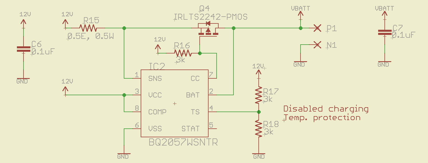
The below figure shows the BQ2057W charging circuit. The following are the design parameters:
1. Vin: 11.4V. The circuit doesn't show a reverse protection diode that drops 0.6V from the 12V
2. Rsns=0.5ohm, 0.5W, 1%.
3. Ireg=0.25A.    Visns=Rsns*Ireg=0.5*0.25=0.125V
3. Vbatt: 6.5V(min) 8.4V(max).
4. Q4 Power Dissipation: (Vin-Visns-Batt_low)*Ireg=(11.4-0.125-6.5)*0.25=1.19W(max)
5. R(theta-air): (Tmax(j) - Ta(max))=150-40=110 degC/W
6. Temperature compensation/protection is disabled.

The IRLTS2242 was selected and has the following spec:
Vdss: -20V, Vgs=+/-12V, Rds(on)=32-55mohm, Id=-7A, Pdmax=2W, Rtheta(junc-air)=62.5 degC/W

You can see that the p-MOSFET selected meets and exceeds all the criteria especially the Rtheta(junc-air). I would like to know if there's a specific parameter that I am not accounting for. Looking forward to hearing from you.

Regards,
Nikhil

  • Hi Nikhil,

    If you're package has a Rtheta(j-a) of 62.5 degC/W , and you are dissipating 1.19W you will see roughly 100 deg C on the FET. You may consider finding a FET in a different package that offers better thermal performance, such as a QFN. You can also try to enlarge the pads, since there is no thermal pad to dissipate heat. Thermal vias around the package will also help heat move to the surrounding ground planes.

  • Hi David,

    Thank you for the prompt reply. I have over 2 sq.inches of area around the chip for heat dissipation with numerous thermal vias to transfer heat to the bottom surface as well. I was hoping that this PCB design along with FET's low Rtheta(j-a) of 62degC/W should've been enough. This was reaffirming especially since the application information of the BQ2057 datasheet the Rtheta(j-c) to be at 90degC/W for 1.2W of dissipation.

    On a side note, are there any non-linear BMS for 2-cell batteries? Like the one's that use PWM instead of linear dissipation.

    Nikhil
  • Nikhil,

    We have many, both with integrated FET's and non integrated FETs. You may want to look into the bq24600 family of chips, if you want external FETs, or the bq24170/1/2 family for integrated FETs are some that come to mind.