This thread has been locked.

If you have a related question, please click the "Ask a related question" button in the top right corner. The newly created question will be automatically linked to this question.

TPS65131 glitch

Other Parts Discussed in Thread: TPS65131, TPS65130

Hi,

My application uses +4v and -3v power supply.

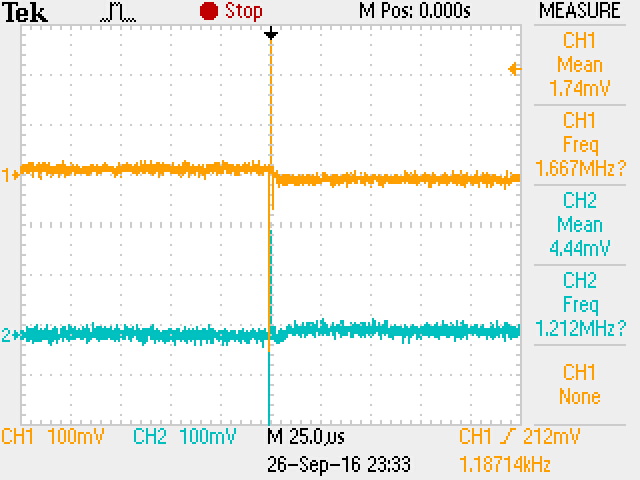
we have chosen the TPS65131, with or without load the voltages are proper. but there is more noise in the power supply output. when the output is observed in CRO the glitches are present. Please let me know how to resolve this issue

  • TPS65131 is a switching regulator.  There is inherent noise associated with switching power supplies.  You may be able to filter them out.  Can you post some waveforms that demonstrate your concern? 

  • Thank you for the reply. 

    I was looking on datasheet, where "To avoid coupling noise into the control loop from the feedforward capacitors, the feedforward effect can be bandwith-limited by adding a series resistor. Any value from 10 kΩ to 100 kΩ is suitable. The greater the resistance, the lower the noise coupled into the control loop system."  I have implemented 10kΩ series resistor in my boards. two boards out of 12 are working fine. but rest have problem.

    Is there any specific calculation for the series resistor?

    I will attach the wave forms soon as possible. 

  • Hello Vinaykumar,

    What happened with the board which are not working properly? The outputs are not present anymore? Could you share your schematic here or in private message?

    For the series resistor value estimation, there is not a simple calculation. I would recommend to try different resistor values in the recommended range given in D/S .
    Having the waveforms would help to determine how to reduce this noise. At what frequency does it appear?

    BTW, what is your application?

    Best regards,
    Diaara
  • Hi,


    "What happened with the board which are not working properly? The outputs are not present anymore? Could you share your schematic here or in private message? "

    -Ya the voltages are measurable, -3V and +4volts, but the ripple is more. since the application is display device, this noise will add up in display image of the display.

    I have tried with 10k, 20k, with nearest about the 100k. there was no change in the wave forms. I tried to replace feed back loop passive components, but still the problem is was not resolved. Please find the attached wave forms. please suggest me to get out of this issue.

    Please let me know mail id to which I can send you the schematic.

  • Hello Vinaykumar,

    The resistors you added to C4 and C27 will not change the glitches you observed on your scope on the output voltages. What you name glitch seem to be the switching noise of the converter and normally the energy content of these glitches is not high enough to cause issues on your display. Especially measuring the real noise on the output is really hard because especially the glitches you show on your scope plot are most probable a lot higher than they are in the system because they are heavily dependent on the measurement setup. Please refer to this blog for more details on this: How you measure your ripple can make you or break you

    I expect that there is something else causing the problems that you observe on your screen. Please try out if the problem with the display is reduced or removed when setting the PSP and PSN pins to GND. PSx allows the converter to stop switching if the output voltage is high enough. The advantage is increased efficiency, the disadvantage is increase output voltage ripple.

    It would be interesting to know which output current you need on the 4V and the -3V for the display you selected.

    Best regards,
    Brigitte

  • hi,

    My display unit need 50mA for -3v, 50mA for +4V.

    since its sensitive to the power supply noise which will effect the image in display. is it possible to eliminate this glitches? by changing any coupling and decoupling capacitors?

    or is there any changes in schematic that can remove this noise? 

  • Hello Vinaykumar,

    Have you tried the suggestion of Brigitte to pull PSP and PSN to ground?

    Best regards?
    Diaara
  • Hello Vinaykumar,

    Do you have any update regarding this issue?

    Best regards,
    Diaara
  • Hi,

    I am trying to change coupling capacitors to reduce this ripple voltage.

    I am trying to put one LC filter after the power supply to check the ripple noise. Please let me know  if any other solution available that I can perform in our lab.

  • Hello Vinaykumar,

    What do you name "coupling capacitors"?

    For the spikes you measured on the scope, it might be helpful to add a cap in the 10nF or 100pF range at the output of the converter.

    Best regards,

    Brigitte

  • Hello Vinaykumar,

    Did this help to solve your issue?

    Best regards,
    Brigitte

  • Hi,
    issue is not resolved, I was trying to add the capacitors at the output side.
    Can you help me choosing this capacitor values, is there any formula that calculate the output capacitor values. In the feedback resistive network can i add one capacitor? please let me know if any formula available for the same.
  • Hello Vinaykumar,

    When I read through the whole thread, I could not get to the basic problem that you have. I could find out that you observe spikes on the output voltage which you do not like, but I did not find out what problem did you want to solve by getting rid of these spikes. Please try to explain to me which basic problem needs to be solved.

    Best regards,
    Brigitte

  • hi,

    sorry that is not coupling, its decoupling capacitor at output side, since as given in datasheet C3 and C4 are output capacitors parallel to the output capacitors I have put 100nf and 10nf for testing purpose. here is the wave forms for output ripple without load. frequency is 530hz.

  • Hi,

    My issue is with the voltage ripple. I want to reduce these ripple voltage. If I reduce this ripple voltage my issue will be solved.

  • Hello Vinaykumar,

    The pins PSP and PSN allow or prevent the IC from going into the power save mode. The ripple looks as if you have low output current and the output is in power save mode. I expect that the ripple is measured on the positive output voltage, so please check if PSP is connected to VIN. If this is the case, please test if your problem is gone when connecting PSP to GND.

    Best regards,
    Brigitte
  • Hello Vinaykumar,

    Could you solve your issue by using the continuous conduction mode?

    Best regards,
    Brigitte

  • Hello Vinaykumar,

    Have you in the mean time solved the problem with the 530 Hz- noise on the output voltage?
    Have you tested the board in CCM (Power safe mode = OFF)?
    If not, could you explain as well your bench-setup? Are you testing only the TPS65130 device on an EVM or is that already implemented in your system? How does the input voltage look like on the device? it can also be coupled noise coming from the mains.. please check the power chain.

    Thank you.
    Best Regards.
    Ilona
  • hi,

    what is 530hz noise, I couldn't get it, my issue was solved by replacing the DIODES, replacing the capacitor and adding capacitor, there was no effect, but the diode change has lot of effects, the noise minimized to some extend.
  • Hello Vinaykumar,

    On Nov. 16th you mentioned that you have 530Hz noise on your output voltage. We just wonder if this issue is gone.

    You mention that your issue is gone by replacing the diodes. It would be interesting for me to understand which diodes you used when the issue occurred and which ones you are using now.

    Your answer sounds as if the problem is solved, so I will set this thread to closed.