We are observing unexpected behavior of your BQ24297 battery charger.
When powering up from Vbus with a battery connected the system powers up in 198mS. This seems very long but would be usable.
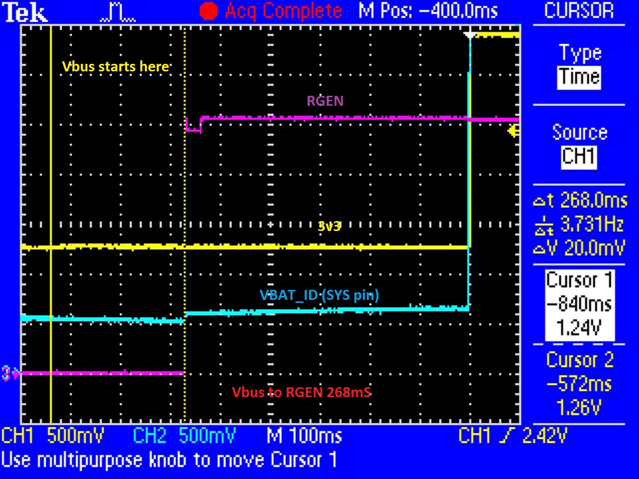
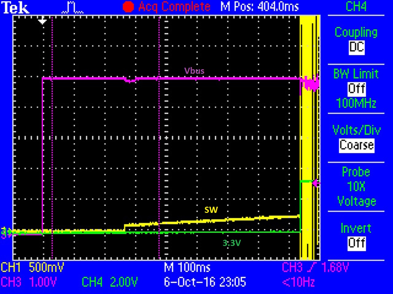
When powering up from Vbus with no battery connected the system requires about 850mS to power-up
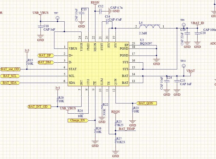
We have the charger pin strapped for 1.5A maximum input current , the OTG pin is pulled to Vbus, and the CE pin is pulled low.
Any idea why the no battery case takes so long and is there anything we can do to fix this.

-
Ask a related question
What is a related question?A related question is a question created from another question. When the related question is created, it will be automatically linked to the original question.