This thread has been locked.

If you have a related question, please click the "Ask a related question" button in the top right corner. The newly created question will be automatically linked to this question.

inrush current problem for bq76940+bq76200

Other Parts Discussed in Thread: BQ78350, BQ76200, BQ76940

Hi Sir,

We design a battery pack (12S2P) to use bq78350+bq76940+bq76200 to implement it but we fouund a problem was as below

.

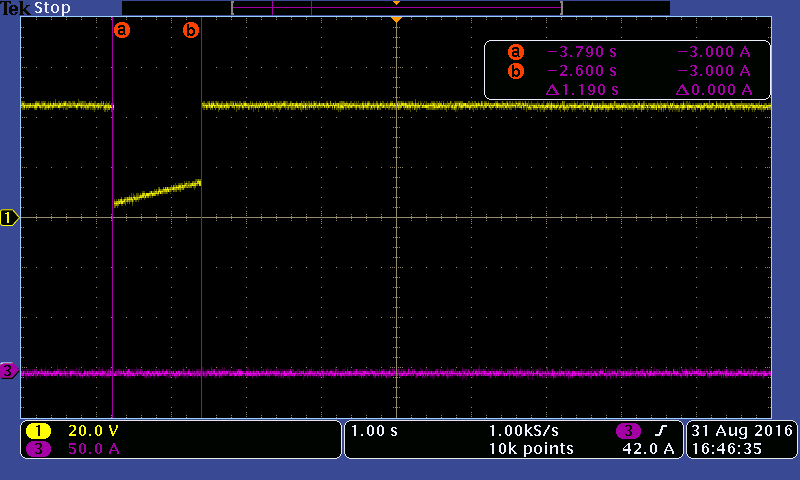
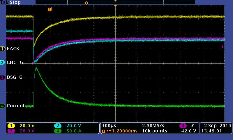
We found there’s an issue of the inrush current testing, please see the normal and abnormal waves as attached.

The test conditions are loaded by 470uF and 1,000uF capacitor, the voltage has dropped drastically with 100us and it has been went back to normal wave around 1s, we tested 10 times but 3 times happened, 30% probability. Can you advise the reason why it is and how to improve it. Thank you.


  • Most likely your are encountering a SCD event at connection of the capacitors, and with some charge still present turn on is successful at 1s.  Since it works 70%, the performance may be close to the threshold and you may see results change with system.  Some solutions below may be possible, be sure to consider the effect on real system SCD conditions as well as capacitive.

    - Increase the gauge ASCD threshold or delay so the SCD does not occur with the capacitance.  The system must be able to take the higher current in other operation.

    - Decrease the ASCD recovery time in the gauge so although it will still have a SCD, it will try to recover more quickly and pump up the output voltage on the load capacitance. The FET must be able to take the current if it is connected to a real short circuit. Use ASCDL settings to allow the FET to cool before trying the sequence again.

    - Increase the gate resistor to the discharge FET to slow turn on.  This won't help the initial SCD occurance but may avoid the possibility of a SCD on the re-try.  A slightly slower edge may reduce the current peak or duration above the threshold. Increasing the gate resistor will also slow down turn off, and too much increase will slow the switching so that CVDDCP on the bq76200 is depleted and turn on will not be successful.

    - Implement a pre-discharge circuit as shown in the apnote for the bq76200.  This is another solution which does not prevent the SCD event but may help with recovery into the capacitance. The bq78350 does not have a feature to control such a circuit, it would need to be controlled on a command from the system.

    - Build in a current limiter.  This is typically undesired due to the complexity and it would function before the system SCD.  In the event of a real SCD the current would continue at the limiter voltage until another overcurrent threshold was reached.

  • Hi Sir,

    I had studied your suggestion solution and confirm the below.

    Increase the gauge ASCD threshold or delay so the SCD does not occur with the capacitance. The system must be able to take the higher current in other operation.

    Confirm: This solution does not improve.

    - Decrease the ASCD recovery time in the gauge so although it will still have a SCD, it will try to recover more quickly and pump up the output voltage on the load capacitance. The FET must be able to take the current if it is connected to a real short circuit. Use ASCDL settings to allow the FET to cool before trying the sequence again.

    Confirm: This solution does not improve.

    - Increase the gate resistor to the discharge FET to slow turn on. This won't help the initial SCD occurance but may avoid the possibility of a SCD on the re-try. A slightly slower edge may reduce the current peak or duration above the threshold. Increasing the gate resistor will also slow down turn off, and too much increase will slow the switching so that CVDDCP on the bq76200 is depleted and turn on will not be successful.

    Confirm: This solution does not improve.

    - Implement a pre-discharge circuit as shown in the apnote for the bq76200. This is another solution which does not prevent the SCD event but may help with recovery into the capacitance. The bq78350 does not have a feature to control such a circuit, it would need to be controlled on a command from the system.

    Confirm: This solution does not improve. We need pre-charge fuction so can't use pre-discharge circuit.

    - Build in a current limiter. This is typically undesired due to the complexity and it would function before the system SCD. In the event of a real SCD the current would continue at the limiter voltage until another overcurrent threshold was reached.

    Confirm: Please help to provide reference circuit of current limiter.

    Thank you so much.
  • A pre-discharge circuit could be built similar to the concept here. https://e2e.ti.com/support/power_management/battery_management/f/1002/p/539498/1966960#1966960 but it needs some control such as from a MCU as discussed here https://e2e.ti.com/support/power_management/battery_management/f/180/t/517349 .

    A current limiter is unusual in a battery, more typically the battery is allowed to deliver all current possible up to a short circuit limit or over current limits.  Current limiting is typically built into the system load or charger.  If you limit current in the battery it will be unlikely to reach the short circuit limit of the battery management subsystem.  Since it is unusual in a battery there is no reference schematic for such a circuit in a battery.  You might search for current limiter circuits, these are often implemented with a depletion mode MOSFET and resistor, or are built into something like a hot-swap controller or switch device.

  • Dear Sir,

    I had studied your suggestion and would like to use MCU (MPS430) to  control the  "Pre-discharge function of BQ76200" but I also need your supporting to verify the below

    1.) How did we use the MCU to control the   pre-discharge? Can you explain the detail operation function to us?

    2.) Can you supply the reference design ( schematic circuit)  to me? 

    Because our customer asked us to use bq78350+bq76940+bq76200 to implement their battery and need to keep keep pre-charge and pre-discharge circuit in the same schematic but also need to  improve the inrush current when   I tested Cload=1000uF. So we need your supporting to improve it quickly. Thank you very much.

    William 

  • This is not a standard solution in an existing part, you will need to select a suitable algorithm and implementation for your system.
    One possibility may be to recognize the DSG line going low with a MCU, ask the gauge the protection status and other conditions, then determine how long to wait before applying the pre-discharge test current and how long to keep it active. Once the gauge has recovered you would turn off the pre-discharge path. If the gauge was not able to recover in your allotted time, you might conclude there is a permanent fault and take some other action.
    There is no schematic available, it is expected the solution would be customized for specific applications.