This thread has been locked.

If you have a related question, please click the "Ask a related question" button in the top right corner. The newly created question will be automatically linked to this question.

BQ76pl455a-q1 usage issues

Other Parts Discussed in Thread: BQ76PL455A-Q1

Hello all,

I am using the BQ76pl455a-q1 for EV application.My aim currently is just to read the registers.I have made a tqfp breakout board, soldered the IC and through jumpers connected other components on a breadboard(I am aware that this design will definitely not give me accuracy in voltage readings as it is not an optimal PCB design but just to initially access registers I suppose this should not pose any problems.)

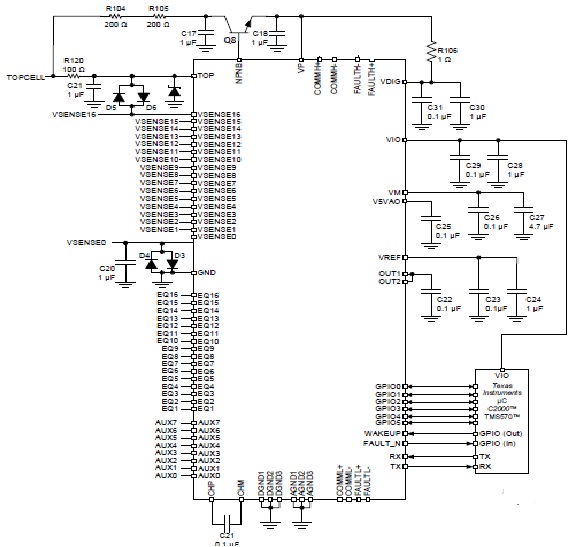
My connections are according to the schematic in the datasheet on page 111 as shown below:

I using a USB to TTL converter to communicate directly through my Windows 10 PC using realterm (The documentation states that any baud rate is possible from the software side and only the PC may pose constraints).The IC is not responding.I'd be glad if someone can help me with this.

1)Should the ground terminal of both MCU and IC need to be shorted?

2) Can anyone please explain me very briefly as to how to exactly issue a frame as the description in the data sheet is not very vivid?

3)What is the exact use of the npn transistor and if we can do away with it(again I could not understand correctly from the datasheet)?

4)How can I be sure that the there is no issue with the IC itself?

Any help would be very greatly appreciated.

Thanks so much.

Regards,

Harsh

  • Harsh,

    1. Yes,
    But, this is just example of one configuration. You can have MCU on low voltage side and have an isolator between.
    2. You can find really good application note in the TI product folder. www.ti.com/.../technicaldocuments
    Check out this site you will find detail example and actual codes.
    3. NPN transistor provides regulated POWERs to VP, VDIG and VIO.
    4. Make sure VP, VDIG and VIO are properly power up. To check this you have to send wakeup signal. This is good way to check initial set-up. VP, VDIG and VIO are 0V until device is fully wakes up. Send a simple command make sure you can communicate to device then I think your set-up and IC are okay.
  • Hello Roger,

    Thanks for your response.

    I am providing a 5.3V input to VP and VDIG externally as I do not have the npn transistor of the parameters stated in the datasheet.So they are always 5.3 V.Moreover,VIO is connected to the 5V supply from the MCU.Is this configuration correct?If yes,then how can I make sure that the IC is functional in this configuration.

    Harsh

  • What baud rate are you using on the UART? The bq76PL455A-Q1 is configured to support only 250Kbps by default. I don;t think Realterm can be setup with that baud rate...