Because of the holidays, TI E2E™ design support forum responses will be delayed from Dec. 25 through Jan. 2. Thank you for your patience.

This thread has been locked.

If you have a related question, please click the "Ask a related question" button in the top right corner. The newly created question will be automatically linked to this question.

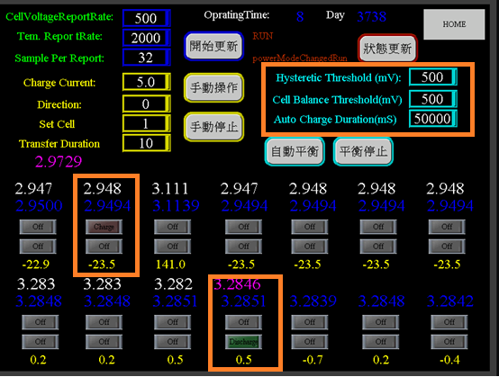
EM1401EVM parameters: Hysteretic and Cell Balance Threshold/Auto Charge Duration no response issue.

Dear Sir:

We used 1 set EM1401EVM for E-Bus battery pack and verified EVM functions.

E-Bus battery pack configaration is 14S 48V.

We test EM1401EVM and found three parameters have something wrong need to comfirm.

We set the value of these parameter to do active battery balance below.

These parameter have no any response to GUI or our UI interface. 

1. Hysteretic Threshold

2. Cell Balance Threshold

3. Auto Charge Duration

At auto and manual active battery balance, the process flow chart of these parameters are different?

Please check this issue..

Thank you so much.

Lucas

  • The firmware provided on the board is for evaluation purposes only. It would be expected that a customer would provide their own firmware for use in a product.
  • Dear Stephen:

    I'm sorry that I described the issue is not very clearly.
    HW is EM1401EVM and FW is included in EM1401EVM that we don't modify FW.
    We used CAN bus to control EM1401EVM and created a user interface (UI) to read/write EM1401EVM parameters.
    When we modified the values of Hysteretic Threshold/Cell Balance Threshold/Auto Charge Duration from UI.
    These parameters have no any response or function to UI.
    Are there actually bugs at the EM1401EVM?
    Could you have any suggestions or comments to us reference.
    Thank you so much.

    HW: EM1401EVM
    FW: stored in EM1401EVM
    SW: Create a UI to read/write EVM1401EVM

    Lucas
  • flash_map_5.pdfHow are you writing the values, as part of the D5 PGN, or by writing the values to Flash with the D3/D4 PGNs? If D5 is not working, please try to write to the Flash registers to change the values. The Flash map is attached.