I am using the TPS2420 eval board to verify operation with another PCB designed in-house. This system needs to operate over voltage ranges of 6-8.5 V. I find that my board/load is only able to power on via the TPS2420 from 6-7.7V, while the range 7.7-8.5V results in a FLT signal enable and the chip goes into reset/restart mode. If I start the voltage lower than 7.7V and ramp up my power supply rail connected to the Vin input of the TPS2420, the chip performs fine. Therefore I suspect the TPS2420 is faulting into either the Hard Overload - Fast Trip or the Overcurrent Protection state. My readings of Vin and Imon do not match any of the application plots in the chip datasheet, so it is difficult for me to tell which mode my load is driving the TPS2420 into.
The steady-state current draw of this board is ~0.6A with operational current draw of up to 3A.
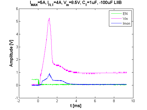
The following plot shows a few signals at the vin=8.5V case, which resulted in a fault.
My settings on the eval board are as follows:
| C_CT | 1uF -> 38.9ms |
| I_MAX | 40.2kOhm -> 5A |
| I_FLT | 50kOhm -> ~4A |
What is the fault mode the TPS2420 is going into? Does the chip read the in-rush current at higher Vin voltages as a a "real, continuous failure" as presented in the datasheet? What can I change on my board/load or, preferably on the TPS2420 surrounding circuit to mitigate this problem?
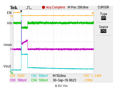
Edit: Here is a long duration plot of the 8.5V Vin case.
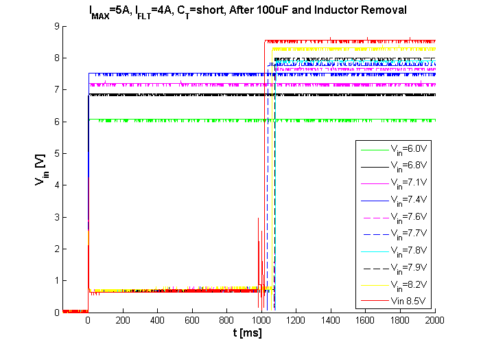
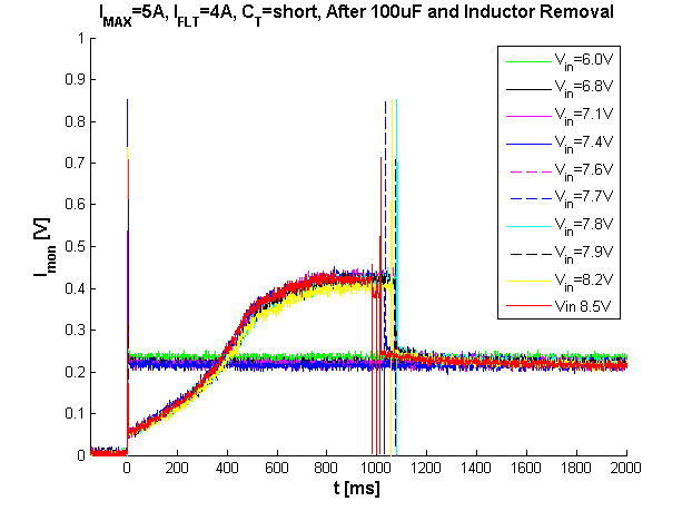
Edit #2: We decided to short the CT capacitor pad in order to bypass the fault detection capability. In addition, we removed our in-line RF bead from the power rail to decrease any inductive loading. We then tested the turn on over the whole range of Vin's. Below are the results for Vin and Imon across the Vin range. With the CT capacitor shorted, the instrument is able to power on within 1050 ms. The cases which resulted in a fault prior to this test take 1050ms to reach Vout=Vin, while the successful "PG" cases from before (<7.6V) reach this state immediately.