This thread has been locked.

If you have a related question, please click the "Ask a related question" button in the top right corner. The newly created question will be automatically linked to this question.

[ LM2936QMPX-5.0 ] about stable region

hi team

LM2936-Q1-5.0 need at least 10uF with ESR 0.3Ohm ~ 8Ohm for stability.

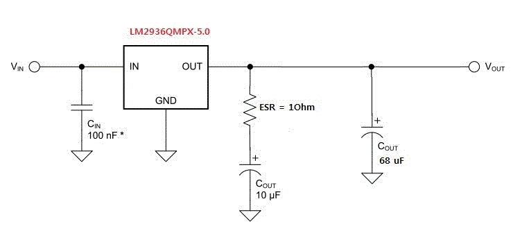
BTW,,, customer made the board as below; 10uF with External ESR = 1 ohm, and 68uF with no external ESR.

it seems the board will make unstable.

my questions are...

[Q1] what is max cout with ESR 0.3Ohm ~ 8Ohm for safe stability for LM2936-Q1-5.0 ?

[Q2] such customer configuration(10uF with External ESR = 1 ohm, and 68uF with no external ESR) can meet stability ?

        if not, tell me why and how to improve the stability ?

  • [A1] As per datasheet there is no limitation for Cout capacitance.

    [A2] Without knowing capacitor type (MLCC, tantalum, electrolytic) it is hard to say. Can you find out that information? If figure is correct both output caps are electrolytic and probably have enough ESR itself. Also layout is very critical. Cout should be as close to the OUT and GND pins as possible.

    Do you have details about Vin condition and load current? Does temperature have any affect for instability? Any scope shots?

    Best regards,


    Jari Niemelä

  • Hi Jari

    in fact, his board has no issue with such two caps configuration,

    but he just asked about such two caps configuration is OK for stability.

    he used Ceramic cap 10uF with external ESR = 1 Ohm which would be OK for stability,

    abd used Aluminum electrolytic cap 68uF which ESR vaule is not known in its datasheet even.

    anyway, I already recommanded him to use the single cap of 68uF ceramic cap with external 1 Ohm ESR for stability,

    because I could not know the exact Aluminum electrolytic cap's ESR.

    BTW,,, my question is,,, what is the correct design for total ESR when using multiple paralle Cout used as below.

    for example,

    the ESR requirement is 0.3 ohm ~ 8 ohm with Min Cout = 10uF.

    at two muliple paralle caps configuration, if ESR1 = 1 ohm and ESR2 = 0.3 ohm, the total_ESR to affect the stability will be 0.23 ohm,

    so that it will make unstable because total_ESR is below min ESR = 0.3 ohm.

    hence, we has to increase ESR2 more up.

    of course, the total_Cout has to be above 10 uF for stability.

    is it right ?

  • Hi Paul,

    Two cap combination should be ok if there is enough ESR on both capacitors. In fact if both ESR's and capacitor's are exactly same value and type they can be calculated as normal parallel circuit. But if there is even a slightly change in type or value transfer function changes and zeros are on different frequencies. So to calculate total ESR and capacitance what a LDO sees you have to calculate capacitor in series with ESR and in parallel with other capacitor and ESR. Hopefully this helps you.

    Your recommendation to use single cap with some ESR would be definitely the safest choice. Just pick ESR value greater than minimum because electrolytics tends to have some hundreds of milliohms ESR anyway.

    Do you know reason why customer wants to use two caps in parallel?

    Best regards,

    Jari Niemelä
  • HI Jari

    i understood your meaning fully.

    BTW... my final question is below..

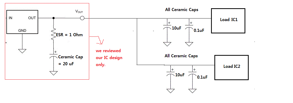
    we reviewed our IC design only to check the desing meet the stability or not,

    but on uesr system level board, normally he mounts a lot of decoupling caps on the Load ICs VCC inputs as below.

    all such caps are typically caramic caps that have very low ESR inside.

    to populate the decoupling caps ov the Load ICs VCC is typical behavior.

    hence, I am worried about such a lot of decoupling caps can degrade LDO's stability.

    could you lend me your expertize that why such a lot of decoupling caps cannot affect LDO stability ?

    thanks a lot. 

  • Hi Paul,

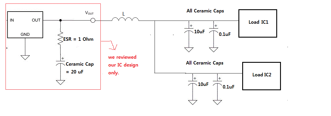
    You have a good point in your question. And there is no one right answer. First of all it is highly system dependent. How long are distances from a LDO output cap to an IC bypass cap, pcb traces resistance and inductance etc.

    Key point on estimating is system/LDO stable or not is a LDO output cap impedance at zero frequency point (fz=1/(2*pi*Resr*Cout)). At that frequency everything which is in parallel ( compined network of bypass caps, pcb traces resistance and inductance) have to have higher impedance than LDO capacitor with ESR meaning that they are not dominating and thus have minimal impact for LDO stability.

    But like said this is highly system dependent. If there is only short and strong traces between LDO output and load device there might be a possibility for stability issues if same size of capacitors as LDO output caps are used on load device inputs. Load devices local few hundreds of nano farads capacitors should be still ok to use.

    There is one old document which enlighten bipolar PNP-type LDO's stability but unfortunately it is not taking care of system level implementation.

    http://www.ti.com/lit/ug/snoa826/snoa826.pdf


    Hope this helps,


    Best regards,


    Jari Niemelä

  • Hi Jari

    thanks a lot for your expertize.