This thread has been locked.

If you have a related question, please click the "Ask a related question" button in the top right corner. The newly created question will be automatically linked to this question.

questions about TPS2553 response time

Other Parts Discussed in Thread: TPS2553, TPS2065C

Hello, Dear Expert. 

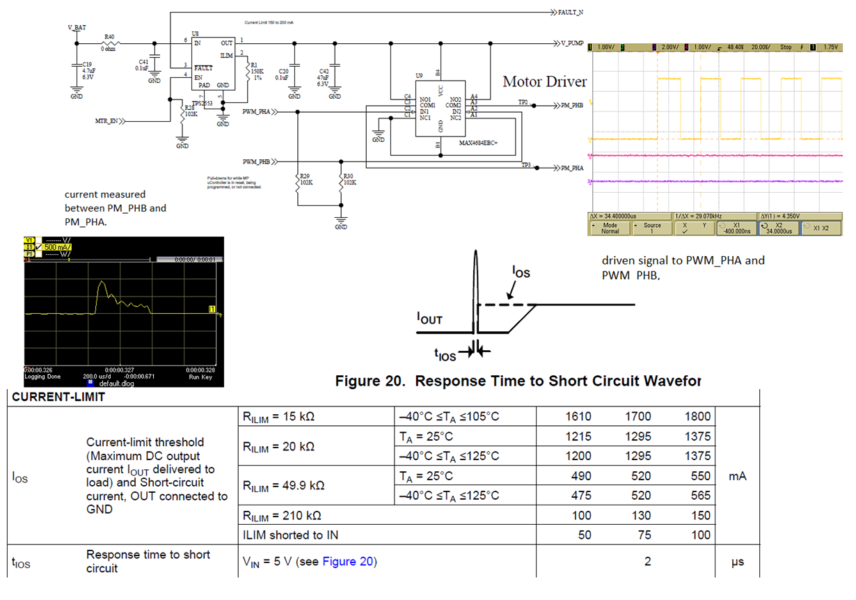
I am using TPS2553 to protect a PWM driven motor.  I did a test to emulate the motor short happen. I noticed that the TPS2553 response time is much longer than the data sheet. 

per my understanding, after the output current over the Ios, which is around 180mA in my design. within tios ( 2us nominal)  the output current will be clamped to Ios.  in my measurement, the current went over  500mA for about 100 us. 

the current is not measured right after the pin 1 of TPS2553, it is after a switch and about 5-inch  wire. will the 47uF output CAP affect the response time. 

how to measure the true response time of this TPS2553. 

thanks,

David Sun

  • David,

    Measuring Tios accurately is tricky. While not shown in the TPS2553 datasheet, a typical test setup will have a very large value of IN pin capacitance (sometimes up to 1000uF in order to keep Vin stable during the surge) and no(or a very small value like 0.01uF for example) OUT pin capacitance to facilitate an accurate measurement of the response time.

    Referring to the TPS2065C datasheet, figure 19 you can see a profile for this measurement. Note that for a softer overload the response time will be longer. In order to get the fast response time, the short must be just a few milli-ohms very near the device and with no effects from an OUT capacitor (the OUT capacitor will help source the current away from the TPS2553 and show up as a softer overload).

    You can also find Figure 28 and 29 from the TPS2065C datasheet 

    For your application, you really do need the help of Cin and Cout and as such, size them so you get the desired performance and the current from the motor does not adversely affect your power supply. You can use the online PSPICE model to help size the supporting circuit values.

  • Hi Eric,

    thank you very much for your prompt response. have a great day.

    David Sun
  • Hi Eric,

    I think it is too ambitious to measure the response time. in fact, I have a more realistic question. Assume I set the current limit to 200mA constant, I will drive it for 300mA for 1ms. and 30mA for 1ms,  and repeat the cycle. if I understand correctly, the chip will clamp the current to 200mA during the first 1ms. and do nothing in the second ms. and if the chip not overheats, the fault signal will never be triggered.  is it right?

    Sincerely,

    David Sun

  • Hi David,

    Let's think of it this way; the "average" current for the load you describe is ~(300mA +30mA) x (1ms/(1ms+1ms)= 165mA which would be below the Ios set point of TPS2553 (200mA). Now, you can size the output capacitor so that during the time when the drive is set for 300mA the capacitor furnishes at least 300mA - 200mA = 100 mA of the current so that the TPS2553 remains on (ie, does not see the Ios event).

    You can size the output capacitor roughly using C = (dT x I) / dV where dT = 1ms, I = 100mA (capacitor current), and dV is voltage droop across the TPS2553 with 200mA current (just below the Ios setting). You can find the Rds-on of the particular device based on package in the datasheet. dV is the Rds-on x Ios. You can choose typical or worst case over temperature using values given in the datasheet.

    For example, if we use Rds-on = 0.1ohm (typical for the DRV package at 25C) we get dV = 0.2 x 0.1 = 0.02 V. Then you would need an output capacitor of ~ C = (0.001 x 0.1) / 0.02 = 0.005F or about 5000uF which is very large.

    Why set the Ios of TPS2553 so low? Is the input source capacity limited? Realistically, the input capacitor (before TPS2553) will help some and the IN voltage will droop also a bit to help keep the switch from hitting Ios. But, if you can tolerate a larger voltage drop across the TPS2553 (ie, let it clamp current at 200mA), then the output capacitor can be smaller. You just need to keep V_PUMP above the minimum VCC operating range of the MAX4684 motor driver IC.