This thread has been locked.

If you have a related question, please click the "Ask a related question" button in the top right corner. The newly created question will be automatically linked to this question.

[ TPS1H100-Q1 ] about design information

Other Parts Discussed in Thread: TPS1H100-Q1

Hi Team

to successfully win TPS1H100-Q1, I need your help.

[Q1] "the Current limit" operation is activated only in the On state ?

        "the Current limit" operation can be activated in the Off state also ?

[Q2] "Short to GND(Overload detection)" can be detected only in the On State( IN Pin = high ) ?

        the device cannot detect "Short to GND(Overload detection)" in the Off state( IN pin = Low) ?

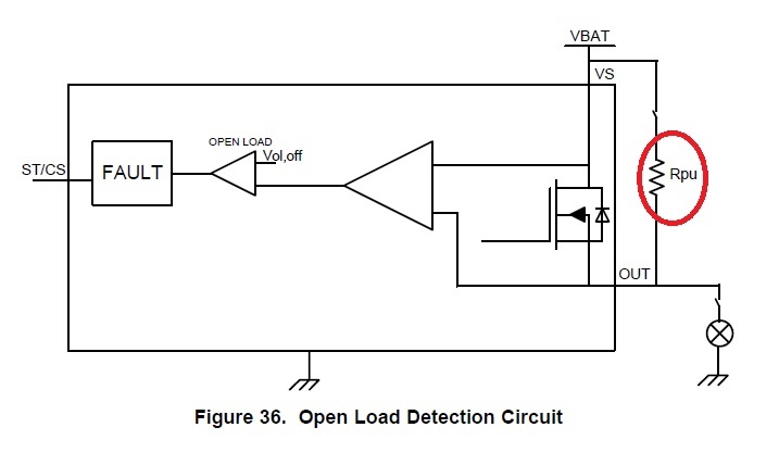
[Q3] the below external pull up resistor needs for both the off-state open load and the off-state short to battery ?

        why we need the external pull up resistor between VS and Vout pins ?

        and if no using the external pull up resistor, what side effect happens ?

        expect very detail explanation.
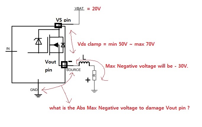
[Q4] what is the Abs max negative voltage between Vout pin and GND to damage the Vout pin as below ?

        in fact, we will apply Max 20V at VS pin, and expects Max - 30V negative voltage at switch off.

        we would like to know such Max - 30V negative voltage can damage Vout pin or not.

  • Hi Paul,

    I have contacted the appropriate engineer and they should get back to you soon.

    Thanks,

    Alek Kaknevicius

  • Hi, Paul,

    The "Current limit" operation and "Short to GND (overload detection)" can be activated only in the on-state. Could you give me more details about your application and explain why you're considering off-state operation? 

    Pull up resistor is used for open-load detection. There is always a leakage current present on the output, and a pull up resistor can be used to offset the leakage current (see datasheet 8.3.4.2). Inaccurate open-load detection can occur without a pull up resistor.

    The Vds is typically clamped around 60 V by an internal clamp circuit in case of huge negative output voltage. A max of - 30 V  won’t damage the Vout pin in your application. You can refer to datasheet 8.3.3 and the figure below for more details.

    Kenneth Du

  • Hi Kenneth

    the end car maker wants to detect "over current" in off-state cause by internal FET Drain-Source short.

    [Q1] can "over current" in off-state be detected by "Short to battery" feature in off-state ?

    [Q2] i cannot understand where the leakage current flowing to and how the pull up resistor offset it.

            could you get your hand maden detail diagram to me for my better understanding ?

           and the pull up resistor needs only for open load detection ? NOT for "short to battery" detect ?

    [Q3] you said,,, Vds clamped at 60V. my application has VS pin = 20V and Max -30V.

            so Vout pin will not damaged because the internal clamp will not activated even.

            BTW,,, if VS pin = 40V and Max -50V, the internal clamp will be activated to protect the internal FET.

            in this case, Vout pin will be damaged ? customer want to know what is Abs max negative voltage to damage Vout.

  • Hi, Paul,

    [Q1] The "over current" can only be detected in on-state. The equation in datasheet 8.3.4.3 “VOUT – VS < VF“ to detect “short to battery” has a precondition: VOUT – VS >0.

    [Q2] The leakage current in datasheet 8.3.4.2 mainly describes leakage current from output to GND, which could pull output low at open load. So we need a pull up resistor to offset it. There is no need of pull up resistor for "short to battery" detection.

    [Q3] The damage of internal clamp circuit relates to the energy of the negative spike. So it is decided not only by the abs max negative voltage, but also the current and time. We recommend Vds is applied below 60V.

    Regards.

    Kenneth

  • Hi Kenneth

    I finished datasheet review and realized that "Short to Battery" and "Reverse Polarity" Detection are using same (Vout > Vs) condition that the reverse current is flowing situation, but "Open Load" detection(Vs > Vout) is totally different from those two in terms of detection detail method.

    However, Table-1 say just one common criterion for "Short to Battery", "Reverse Polarity", and "Open Load" detection,

    so that i was very confused to figure out those 3 detection methods correctly.

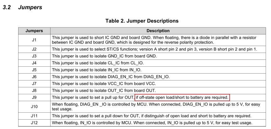
    further, EVM said we needs the pull up resistor for the off-state open load/short to battery detection,

    so I asked  the pull up resistor is needed for "Short to battey" also.

    appreciated your help. thanks.