This thread has been locked.

If you have a related question, please click the "Ask a related question" button in the top right corner. The newly created question will be automatically linked to this question.

TPS65130 VPOS and VNEG Problems

Other Parts Discussed in Thread: TPS65130

Hi,

I am using the TPS65130 to generate a +/-15v supply, with max load current 50mA, please find the attached schematic.

TPS65130_SCH.pdf

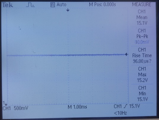
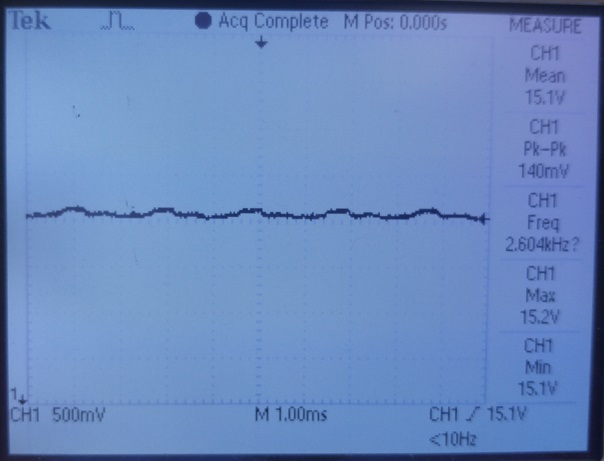
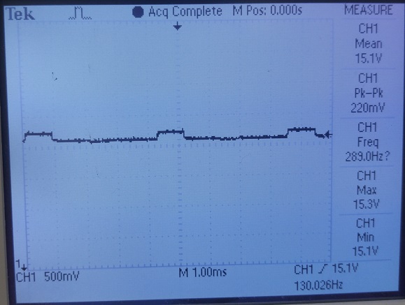
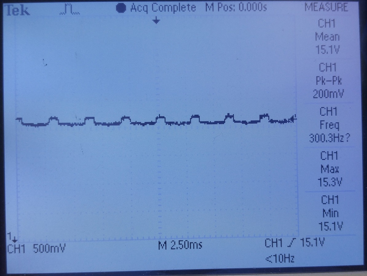
On the positive rail (VPOS pin), the output changes between 15.3v and 15.1v, as shown in the following image:

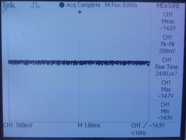
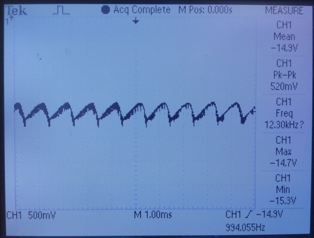
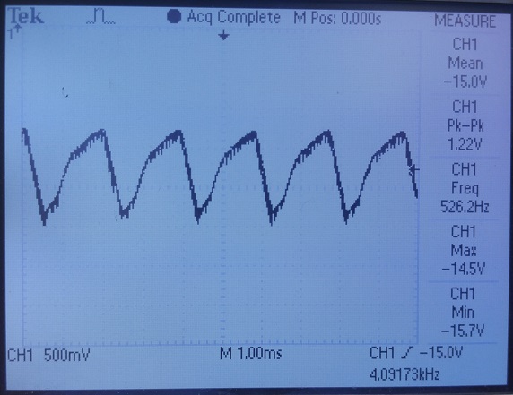
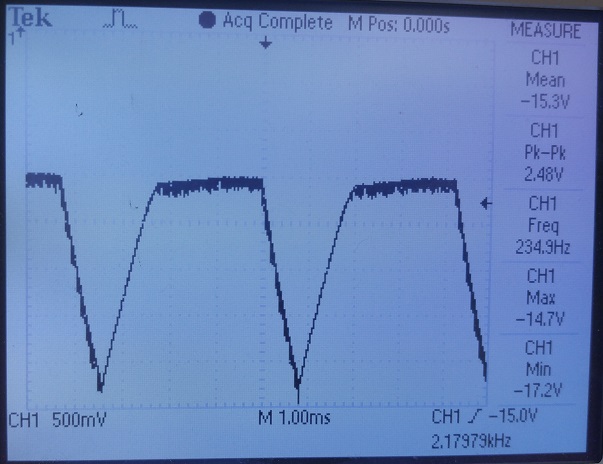
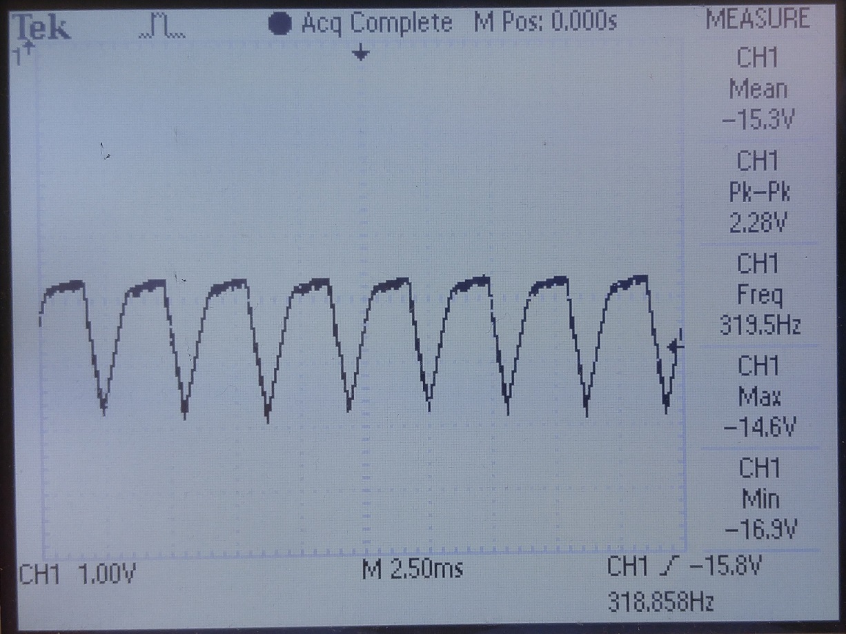
On the negative rail (VNEG pin), the output is fluctuating between -17v and -14.6v, as shown in the image:

I have noticed that increasing the supply voltage from 5v to 5.15v solves the problem on both rails.

Best Regards,

Mostafa

  • Hello Mostafa,

    Thanks for your enquiry. Can you maybe show a scope plot with the voltages and the inductor current? What happens if you decrease the input voltage to let's say 4.5 V or 4 V. Do you see the same oscillations?

    On your schematic you are using a 22 uF capacitor. If this is a ceramic capacitor it is likely that the effective capacitance is too low and that can cause instability or/and oscillation. The recommended effective capacitance (DC bias) for this converter at 15 V output is 10 uF.
    What is the reason that you are using an electrolytic capacitor on the negative output? Usually we do not recommend ELCOs as they have much higher ESR and that increases the voltage ripple. Can you send me the part numbers of both output caps?

    Thank you.
    Best Regards.
    Ilona
  • Hi Ilona,


    Thank you for your reply.


    First, the output capacitors used in this schematics are:

    • C13 - 22uF - Ceramic: GRM32ER61E226KE15L
    • C18 - 27uF - Aluminum: UUD1E270MCL1GS

    The aluminum cap was the one available with the 27uF capacitance.

    The ceramic cap reaches about 9uF @ 15v bias.

     Another thing, the inductors used for the VPOS and VNEG rails are different:

    • VPOS – 4.7uH : LQM2HPN4R7MG0L
    • VNEG – 4.7uH: VLCF4028T-4R7N1R5-2


    I tried operating the board with different supply voltages, and found the following:

    1. Between 3.3v – 4.1v the outputs from +/-15v rail are stable.
    2. Starting from 4.2v ripples starts to appear on the output of the negative rail, while 15v remains good.
    3. From 4.5v – 5.2v, ripples start to appear on the +15v rail, and the magnitude of the -15v rail ripples continue to increase.
    4. After 5.3v the output of both rails is OK.

    Supply (v)

    VPOS

    VNEG

    3.3

    4.2


    4.5

    5.2


    What do you recommend?


    Many Thanks,

    Mostafa Sakr

  • Hello Mostafa,

    Did you already check the output voltage behavior when you change the output capacitors to low ESR, high capacitance types? It is possible that such a behavior is caused by too little output capacitance.

    Best regards,
    Brigitte