This thread has been locked.

If you have a related question, please click the "Ask a related question" button in the top right corner. The newly created question will be automatically linked to this question.

TPS61222 true output current and stability across temp issues

Other Parts Discussed in Thread: TPS61222, TPS61240, TPS61070

Hi team,

I have a customer looking to use the TPS61222 to boost a Lithium+ cell (so 3V-4.2V) up to 5V with output current of ~70mA. This seems like it should be fine according to this graph in the datasheet:

This graph says that 3V in, 5V out should be capable of 150mA. However, when simulating in Webench it returns that 150mA Iout would breach the switch current limit. So, this is one discrepancy.  

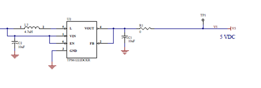
Then, when simulating in webench at 70mA output, it says it will be marginally stable, but when applying hot and cold temp to the part under those conditions, the 5V output becomes unstable (-20C to 60C). Here is the power supply:

I found that this matches almost exactly this diagram in the datasheet, which says it only outputs "up to 60mA"

I tried to calculate the max output current myself but I didn't really have enough information to do so since the switch current limit in the datasheet is spec'd at 3.3V out...using those values anyway though, I calculated 68.4mA so that doesn't really match.

So in summary:

  1. Why did webench say these conditions breached the switch current limit, when the datasheet says it should be capable?
  2. What is the true output current capability of the part at 5V out?
  3. Any ideas on why my customer's power supply is so marginally stable that a little temp change causes instability?

Thanks,

Brian

  • Brian
    considering the worse case, the average input current limit is approximately IIN= 120mA, so we can calculate the maximum output current at 5V is 65mA from VIN=3V (IIN*VIN*0.9/VOUT). the maximum output current figure is just for typical condition, and tested with an EVM.

    i would suggest TPS61070 or TPS61240 for this application.
  • I'm not sure I understand why that graph is included if it's contents don't apply. Also, where is the Input current spec? I can't find that in the datasheet...

    I am not sure how somebody can figure out the max output current at a specific use case themselves with what is currently in the datasheet.

    Thanks,

    Brian

  • we can only specify the SW peak current limit, the minimum value is 240mA at 25oC and 200mA at -40~85oC. the current ripple is approximately 200mA, so the average input current is 140mA (min) at 25oC and 100mA (min) at -40~85oC.

    The maximum output current at Figure 1 of the datasheet is measured in the EVM, the current limit of the typical EVM is approximately 400mA. that is why the maximum output current is much higher.
  • Jasper,

    I am still a little unclear why the part is capable of more output current on the EVM than in another application....

    Edit:

    I think understand now. So, I should be calculating output current using the 200mA min Switch Current Limit to account for tolerance and temperature, not the typical 400mA number. That 400 number is likely where the part on the EVM landed.

    Is that limit still 200mA if my output voltage is 5V instead of 3.3V?

  • Yes. output voltage has little impact on the current limit.
    from my experiment, it is low risk to trigger current limitation at VIN=3V, VOUT=5V & 70mA for TPS61222. but a safer way should be selecting a higher current limit boost converter.