Hi
I have a custom PCB with the bq40z60 on, and followed the reference design closely, so I dont think there is a problem with the hardware. I the only difference should be that I have a "normal" fuse, not one that the PCB can trigger.
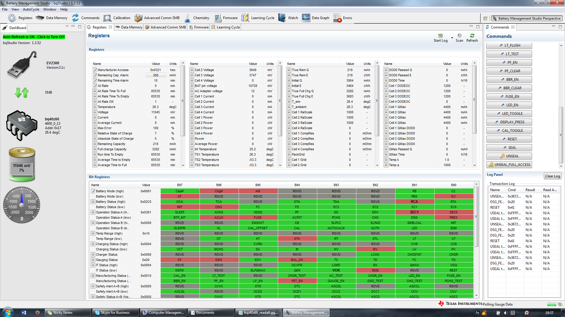
I have attached the .srec file and screenshot of registers, everything below what is in the image is all green. I have tested on two cards, the last one has the default config, only changed to set one temperature sensor and enabled FET_EN (also set remaining alarm to 200 to remove alarm). This is on a 3 cell lipo. Charging voltage was connected with 15V, but was disconnected when I took the screenshot
So, the problem is that I cant activate any of the FETs, in the first case, the DSG FET. I would think that it would be turned on when powered now, but it does not. Also, the OperationStatus[DSG] and OperationStatus[CGS] are disabled, I assume that this means that there is something preventing the bq40z60 from trying to activate them? I have tried to disable FET_EN and manually activate the DSG with DSG_TEST, but it is the same result. No OperationStatus[DSG] and no current flow.
Does this have anything to do with the OperationStatus[FUSE]? I havent found a way to disable/ignore that.
Also, the GaugingStatus[CF] and BatteryMode[CF] are active, does that the learning cycle should be run? I have tried that, but it does not work as long as the discharge FET is not ative.
I have looked around the forums, but not found anything similar, so I hope somebody here has some idea. Hopefully there is a stupid thing I have overlooked.