A related question is a question created from another question. When the related question is created, it will be automatically linked to the original question.
If you have a related question, please click the "Ask a related question" button in the top right corner. The newly created question will be automatically linked to this question.
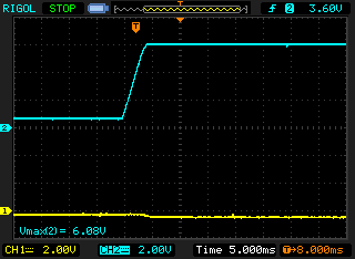
Thank you for the schematic; however, to help debug your application, more information is needed. A scope shot showing Vin, Vout, and Iout would be helpful.
Please note that a common cause for Vout drooping as you describe is an unintentional current path caused by flux. Please check for flux residue particularly around the feedback network.
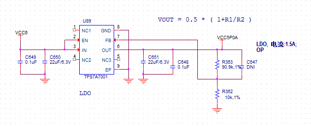
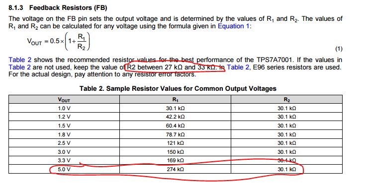
One thing to point out with regards to your schematic is that your resistor divider is not within the operating range listed in the datasheet:
Thank you for the scope shot. It looks like you are pulling the output of the LDO negative before it starts up. As a result, the LDO is not able to properly startup. This implies that you have a negative voltage in your application that is starting up before your TPS7A7001 and is biasing the output via a leakage path (likely in the load of the LDO. Most likely all you need to do to fix this is to sequence the TPS7A7001 before the negative rail.
The TPS7A3301's enable can be driven from a +5V. So if you either put an RC from VCC6 or give a fixed delay with something like the TPS3831 or TPS3890, you can ensure that the positive rail turns on before the negative.
Hi John,
In our application, positive rail turns on before the negative.
when power down, after seconds power up again, tps7a7001 output is negative.
when power down, there is a negative voltage on the output of tps7a7001, then power up again, tps7a7001 output is negative(around -0.4V).
When power down, how can we make the negative voltage on the output of tps7a7001 disappear as soon as possible?
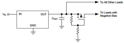
There are a few application work around concepts that can help when an LDO is negatively biased. It seems that the last two will be more useful for your application.
Enable the device before the negative regulator and disable the device after the negative regulator.
Use an external pulldown resistor.
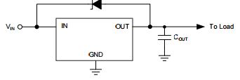
Place a zener diode from IN to OUT to provide a small positive dc bias on the output when the input is supplied to the device.
Use a PFET to isolate the output of the device from the load causing the negative bias when the device is off.