This thread has been locked.

If you have a related question, please click the "Ask a related question" button in the top right corner. The newly created question will be automatically linked to this question.

TL431 based Series Pass Regulator

Other Parts Discussed in Thread: TL431, TLV431, ATL431

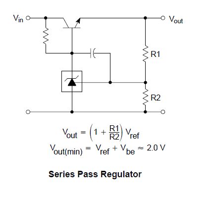
1. The Resistor on the left is connected to limit the current flow through Cathode to Anode of  TL431.  How to select that resistor ( consider Vin varies form 200 V to 700 V )?  It is given that Ika = 1mA -100mA? Suppose if I choose a resistor high enough to limit the current, say 500K. gives 1.4mA for 700V and and 0,4mA during 200V. So, Will it be functioning during 200 V?   I am going for very high limiting resistance to minimize the power dissipation in TL431 as low as Possible.

2. And also I want to limit the current flow in NPN transistor, where should I place Resistor in collector terminal or emitter terminal ?

3.What is the need of the Capacitor Cathode and reference  and How to select the Capacitance value? Could anyone please explain it ?

  • Hello Arumugam,

    I would like to question what you are trying to do here because 200V to 700V down to say 12V, is a lot of voltage drop and any current flowing through the NPN is going to create a huge amount of power consumption. Likely so much so that the power consumption of the TL431 will be inconsequential.

    Additionally, on startup, if the TL431 is not regulating maybe even for a short time then the cathode could see the very large 200V - 700V. This is not recommended because the TL431 can only handle 36V maximum at the cathode.

    1. You need to select the resistor to help bias the tl431 device with enough current to regulate at the reference. Although typically, 0.4mA is enough for regulation, it is generally recommended to design for at least 1mA of current into the cathode to ensure regulation over operating conditions. If you are trying to reduce consumption further, you could consider using the TLV431 because the cathode current for regulation is on the order of 100uA as opposed to 1mA for the TL431.

    2. A series resistance in the current path will not help to limit current, but rather consume power or step down voltage based on the current consumption. If you are trying to limit current you will need to implement another type of circuitry. You could refer to the following blog for current limiting with voltage references.
    e2e.ti.com/.../can-overcurrent-protection-be-simple-and-precise-while-minimizing-cost

    3. This can help stability and help to slow down the rise of the output voltage.

    Best,
    Michael
  • Dear Michael J Schultis ,

    Thank you very much for your detailed reply. Actually I am trying to design a Startup Circuit for DC DC Converter using TLV431 based Series pass regulator ( say Vout = 12 V, Iout = 11.8 mA, constant current output irrespective of line variations ). And this series pass regulator will be operating only for 50ms and I trying to put it off, by using bias winding output say(15V). What I actually trying a design Constant Current Source for my Bias capacitor using TL431 during Startup period say 50ms? Calculated Cap to Supply required Current is 48uF. Could you please suggest solution for this requirement.

    How the Capacitor between Cathode and Reference improve the Stability and helps to slow down the output voltage rise ? How to choose that value. If possible share any app note/ any reference which explains need and operation of that Capacitor .

    Once again, Thank you very much Michael for your time.

    Regards,
    Aaru
  • Hello Aaru,

    If I understand what you are trying to achieve, in terms of setting a constant current, then I would recommend a different circuit.

    Here is a link to designing a constant current source with the ATL431, a newer version of the TL431.

    https://e2e.ti.com/blogs_/b/powerhouse/archive/2015/07/31/can-overcurrent-protection-be-simple-and-precise-while-minimizing-cost 

    If you have further questions please let me know.

    Best,
    Michael