


Hello,
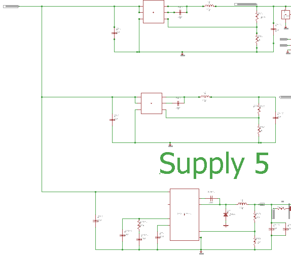
My group and I are working on a project, and we're having a problem trying to read outputs from our DC/DC converter circuit. We're using 3 different TPS converters as listed in the "Subject" (TPS562200, TPS563200, TPS54332) to get the 3 different voltages that we need. But right now when we provide a power source of around 10-14V from a battery, we're not getting any voltage for the output. We're expecting to receive voltages of 3.3V, 5V, and 12V. I included here the schematic of our DC/DC circuit, and was wondering if someone could help take a look at it and see if there's anything wrong, know why we're not receiving any output. or have suggestions on what we can do to test the circuit. Thanks!
- General Overview
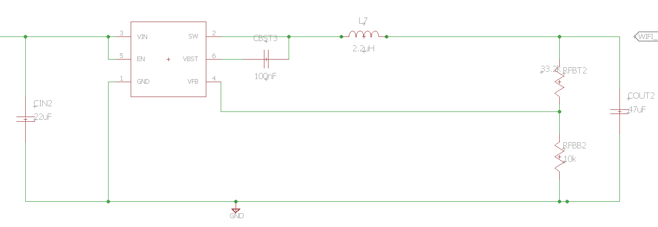
- Supply 1 (5V)

- Supply 2 (3.3V)
- Supply 3 (12V)


