


Hello,
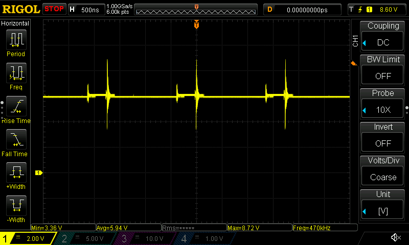
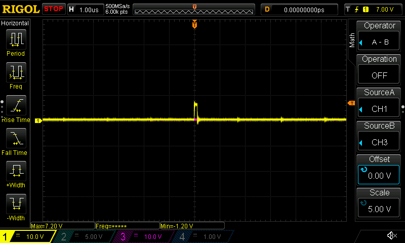
I am solving several field failures of a device using the BQ24650 that is already in production. Some of them have rather strange behaviour in the HIDRV and PH nodes. In this group of failures, the devices have all signals working correctly, with exception of HIDRV, PH and MPPSET . Please see the following scope captures:
HIDRV pin reference to GND

Vph referenced to ground:

So this waveforms are not of normal operation of the device. I understand HIDRV is 6V higher than PH when enabling the High side mosfet. So here is a waveform of HIDRV referenced from PH, which is exactly Vgs of the high side mosfet, for reference:

What could be the cause of that strange waveform that 1) has that ringing and 2) is driving the high side mosfet for a very short time. I think this is the reason why MPPSET can not be correctly performed and is at 1.4V instead of 1.2V.
Following are waveforms of all other related signals for you to understand the status of the device:
Vts referenced to GND (seems OK)

**************************************************************************************
Vfb referenced to GND (sems OK)
**************************************************************************************
Vref referenced to GND ( ~3.3V, seems OK)

**************************************************************************************
Vregn referenced to GND( ~6V, seems OK)

**************************************************************************************
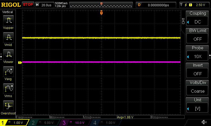
Vmppset referenced to GND (1.32V, sometimes 1.4V, not ok)

**************************************************************************************
Vbtst referenced to Vph, (not OK, should be very stable at ~6V)

Vbtst referenced to Vph from a known good board (
**************************************************************************************
Vcc referenced to Vsrn: Vcc >> ( Vsrn + 100mV) , actually Vcc is aprox 7.44V above Vsrn so the device is definitely ON.

**************************************************************************************
Vlodriv (does not look ok, just as hidrv, does not seem it is switching fast enough)
Input:
Solar Panel, 15W, Voc23V, Vmmpt ~ 16.5V, 10m cable length. I am using a real panel, not using a bench supply to simulate it. In either case the behaviour is the same.
Output:
Sealed Lead Acid battery, 12.6V, 12Ah,
Sense Resistor 20mOhm,
Per the charging enable/disable requirements listed in Page 14 of the BQ24650 datasheet, all charging conditions are OK.
STAT1 pin is LOW, indicating a charging is in process.
STAT2 Pin is high (14.34V). The combination of STAT1 and STAT1 indicates NO FAULT DETECTED.
I can provide full schematic via private message.
I will appreciate your help to identify the issue in this set of boards.
Thanks TI Team
