This thread has been locked.

If you have a related question, please click the "Ask a related question" button in the top right corner. The newly created question will be automatically linked to this question.

LM3481 & LMR62014 Schematic Review Request

Other Parts Discussed in Thread: LMR62014, LM3481

Hello,

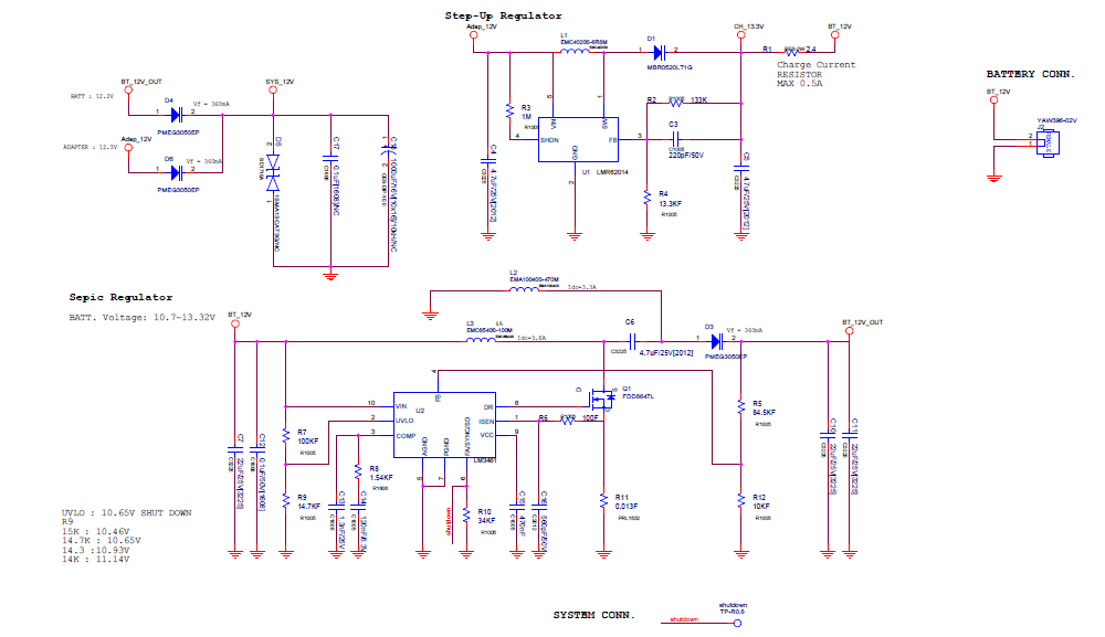
One of customer wants to make LEAD ACID Battery Charge / Discharge circuit as attached.

Could you review it and let me get the result?

  1. LEAD ACID Charge  : Step-Up Regulator : LMR62014 out  13.3V
  2. LM3481 out  12V  to System power
  3. LM3481  Power off if Vin drop under 10.7V 

Regards,

Nicky

  • Hi Nicky ,

    Please find below my comments on LM3481 SEPIC design :

    1. With the uncoupled inductor in SEPIC , the measurement of the loop gain will show a high-Q , low frequency resonance which will need addition of an R/C damping filter in parallel with AC capacitor C6(in Schematic).The resonant frequency, while greatly simplified, appeared to be approximately 

    The R/C damping needed to be placed parallel to  Cac cap C6 is series combination of 47uF/25V and 6.8 ohm .Below is the change in gain and phase you would see with the insertion of damping components .

    2. Rest all seems OK to be . 

    --Ambreesh 

  • Hi Ambreesh,

    You recommend "series combination of 47uF/25V and 6.8 ohm".
    Is there any specific option for capacitor(Ceramic, Elec. Cap or Tantal....etc) and resistor(Power rating...etc)?

    And 47uF is too big capacity. Could you let me know the minimum capacity?


    Regards,
    Nicky

  • Hi Ambreesh,

    Could you let me get the answer about Capacitor and resistor spec?

    Regards,
    Nicky
  • Hi Ambreesh,

    You recommend 47uF/25V + 6.8ohm parallel damping circuit to C6.

    Could you explain how those capacitance and resistance value come out?

    And also let me know the resistor power rating. Can I use normal 1/10W (2012 size) resistor?

    Sorry for rush you, but please let me get your answer ASAP.

    Regards,

    Nicky

  • Hi Nicky ,

    The RC damping filter is used to filter out the LC resonance happening at 10KHz approx in your design . You may use electrolytic Cap for damping C with positive terminal being connected to FET side and the dissipation across the resistance is smaller than 100mW so 0805 or 1206 should be OK for the design . The other option is to use coupled inductor for the design . You may find more details here
    www.ti.com/.../slyt411.pdf

    ---Ambreesh