Because of the holidays, TI E2E™ design support forum responses will be delayed from Dec. 25 through Jan. 2. Thank you for your patience.

This thread has been locked.

If you have a related question, please click the "Ask a related question" button in the top right corner. The newly created question will be automatically linked to this question.

TL494 DTC issue

Other Parts Discussed in Thread: TL494

Dear support.

Our customer's TL494 didn't work at market.
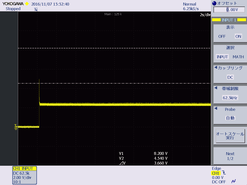
When checking this device, DTC was working as follows.
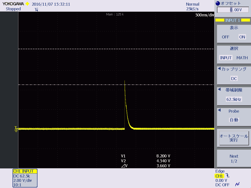
The normal DTC waveform is as follows.
Why will the voltage of DTC of this device be 2.3V?
If you need customers schmatich, please send me email directly. (pls. see my profile)

Best Regards,
PAN-M

  • You can send the schematic to me directly. j(dash)tucker(at)ti(dot)com
  • Hello,

    In looking at the schematic provided, I am seeing that the DTC pin is being controlled by an amplifier that is connecting a 5V line to the DTC pin. If the Q900 output is disconnected from the DTC pin, does the voltage still stay at 2.3V. If it does, then its possible that the DTC pin is getting damaged, but I don't believe this will be the case.

    I think something may be happening with the IC900 output that is connection the 5V through the PNP to the DTC pin. If the Q900 collector is disconnected, does the DTC pin get pulled low by the pulldown on the DTC pin?

    Best,
    Michael

  • I don't pulldown this point, but even if Q900 is removed, it's same.
  • Hello,

    I see that R905 is pulling this point down? Am I mistaken?
    I only see that a 10k is pulling the DTC to ground and the Q900 collector is also connected to this point. The DTC pin is a high impedance input put, so the external circuitry should define the voltage see at the DTC pin.

    Is what I am seeing on the schematic incorrect? Can you help explain what is connected to the DTC pin if I am wrong?

    Best,
    Michael