This thread has been locked.

If you have a related question, please click the "Ask a related question" button in the top right corner. The newly created question will be automatically linked to this question.

BQ24040 charging current

Other Parts Discussed in Thread: BQ24040

Hello

We are implementing the bq24040 to charge a Lion 2150mAh cell (BMS included). the chip is configured to deliver the maximum charge current 1A at CC  mode, the schematic (SCH) is shown below:

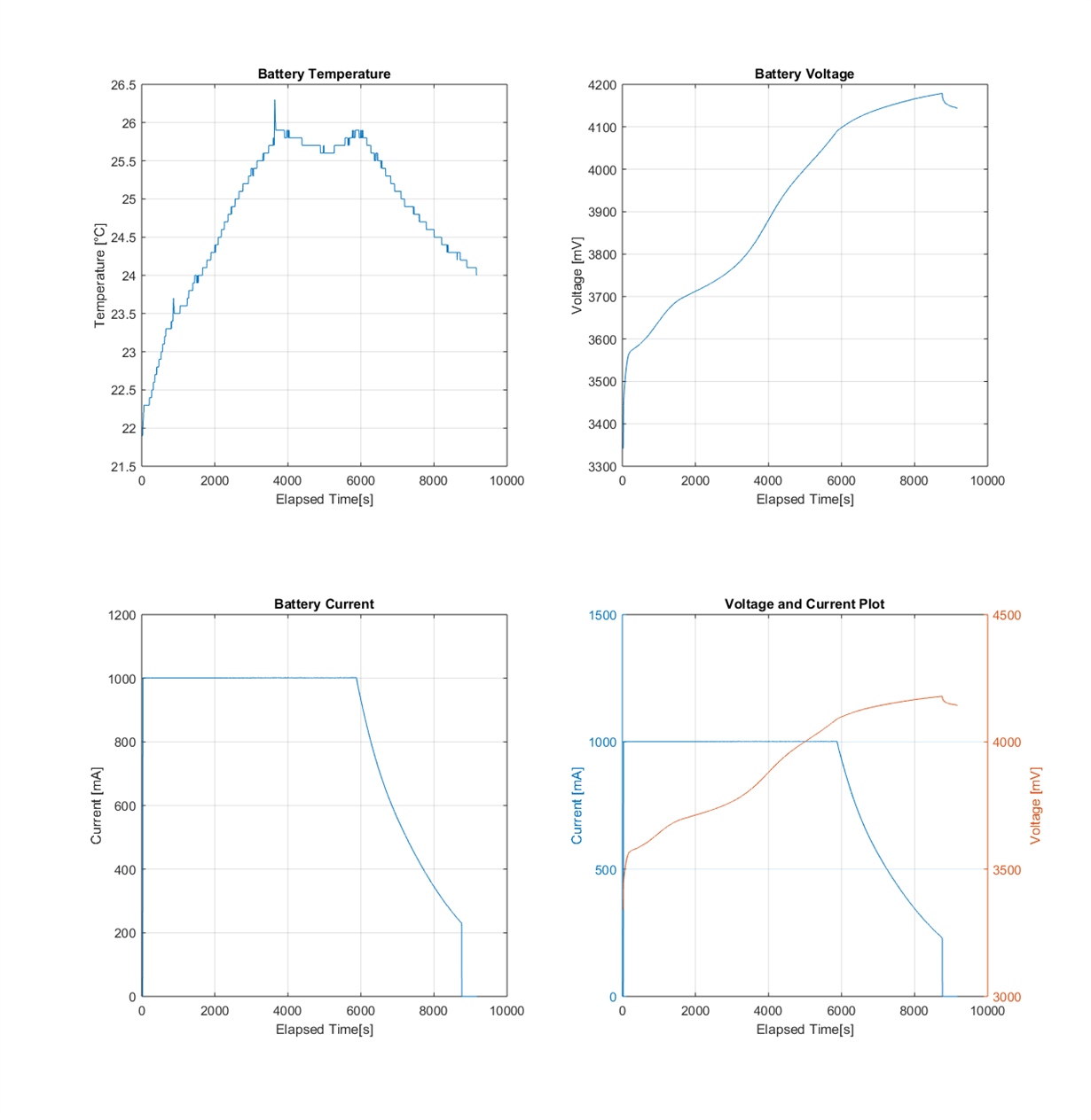
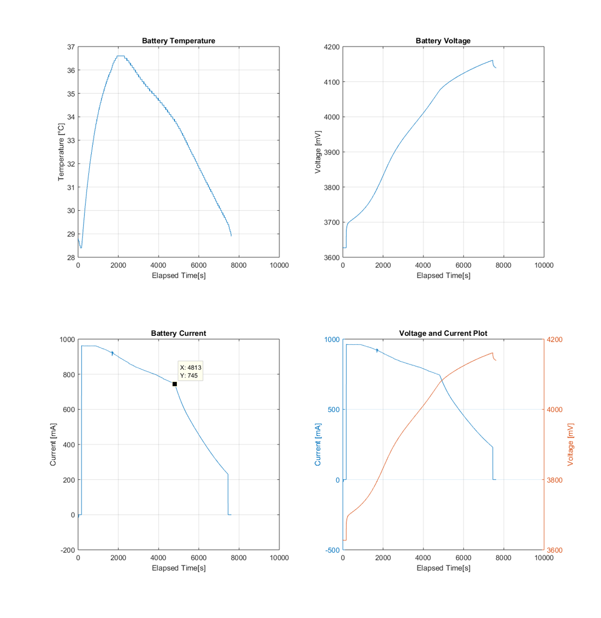
When connected to the cell, the charging current is dropping along the charging process. It looks like, for some reason, the charger is limiting the charging current.

Cell charged with external power supply unit:

Cell charged with bq24040:

a) Is this normal?

b) If negative, how can a fix this issue?

Thanks in advance

  • Hi guys
    Could somebody help with this? Our company and I will really appreciate it
    Thanks in advance
  • Hi Julio,


    Sorry for the delay in the response. How does your layout look? Is the IC getting hot? There may be thermal regulation occuring.
  • Hi David

    I am attaching the charger layout of our HW (layer by layer) and a thermal picture of the device when it is charging the battery.

    Top layer:

    Int01 layer:

    Int02 layer:

    Bottom layer:

    Thermal Picture:

    a) According to bq24040 datasheet, thermal regulation only occurs at 125°C, Do you think that the chip reaching that temperature?

    b) I noticed that during charger operation, the voltage across RISET is dropping from 1.5V to less voltage. Our passives components have 1% tolerance and I verify that there is no change in their values before and after the charger operation. Is this input been affected by the chip temperature?

    c) What do you recommend to do to solve this issue?

  • Julio,


    Hmm, you are correct about thermal regulation occurring at 125C. It looks from your thermal capture that it is only ~63 C.

    Can you measure the voltage at the TS pin?

    Your charge current is definitely being reduced, but it doesn't seem to be regulating it. Your resistors are close to the IC, can you see if they have a temperature coefficient? With the timescale involved, the resistor might be heating up with the IC and changing it's resistance.


    Can also measure your input voltage during this time?
  • Hi David

    We detected that our layout is not conducting the heat properly. At the outside the temperature is close to 63°C but internally is something around 120°C due to the Junction-to-case (top) thermal resistance at the power dissipated. I confirmed this repeating the charge test and adding an external heatsink.

    The temperature in the chip top section was around 51°C and the output current behaved as expected. The voltage-current profile is shown in the figure below:

    The layout changes to solve this issue have been done. The new test will be performed on the new PCB version and then the issue will be officially solved.

    Thanks for your help

  • Julio,

    Thanks for giving me the update! I'm happy to hear that you got it figured out. Let me know if you need anything else.