This thread has been locked.

If you have a related question, please click the "Ask a related question" button in the top right corner. The newly created question will be automatically linked to this question.

I have some question about tida-00329 with bq51051B

Other Parts Discussed in Thread: BQ51051B, BQ51050B

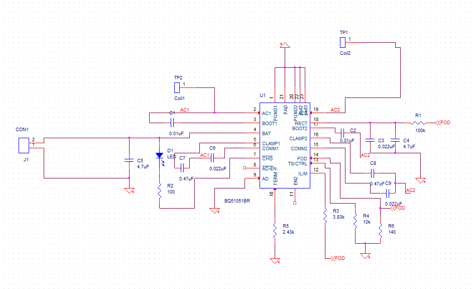
hello I'm try to make tida-00329 design with bq51051b.

above is my circuit diagram and it's working

but, what i want to do is monitor status with diode. 

1. is it ok to connect diode between BAT and ~CHG pin? what value of resistor preferred? 

2. Power receiving distance

tida-00329 works with coil wr22230-26m8, power transfer(coupling) distance is about 1~2mm I think.

is there any possible way to longer this distance? about 4mm?

possibly fixed resonant frequency of receiving can boast distance?

or shape and size of each coil(transfer, receiver) can longer the transferring distance?

and also i want to know about self-resonance method used in tida-00329 is there any technical support about this?

  • Sukkyu,

    1)  Yes, an LED can be placed from BAT to ~CHG.  See the bq51050B EVM User Guide for an example.  Note that for low battery situations (2.5V for example) there may not be enough voltage to light the LED.  Check the VF of the LED for your system.  The default resistor on the EVM is 1.5k.

    2)  The TIDA-00329 does work with the right combination of RX and TX up to 5mm.  Alignment will have an impact on power transfer.  Size and shapes of the TX and RX coil will definitely have an impact.  See TIDA-00334 for an example of a smaller TX coil.  The TIDA-00415 is an even smaller TX coil.

    3)  Since the TIDA-00329 was used to demonstrate small solution size, there were no resonant capacitors added.  That means the resonant frequency was not set to 100kHz.  In the standard WPC (Qi) solution, both TX and RX are set to 100kHz.  The TIDA-00329 will function in most cases, but efficiency may not be optimized.  You can set the resonant frequency if needed by following the procedure set up in the datasheet.

    I did not note any issues with the schematic.  Make sure the capacitors on the AC1 and AC2 pins are 25V or greater.

    Regards,

    Dick