This thread has been locked.

If you have a related question, please click the "Ask a related question" button in the top right corner. The newly created question will be automatically linked to this question.

BQ24250 EN1/EN2 and Chrgr_Reg2

Other Parts Discussed in Thread: BQ24250, EV2400, BQ27532EVM-656

Good day.

As far as I understand, bits 0 / 1 of Chrgr_Reg2 show me state of EN2 / EN1 respectively.

I have tried to config them to 0 / 0 and 1 / 0, but I ALWAYS see there both 0 and 0.

What may be wrong?

Additional question.

We are using pair BQ27532 + BQ24250. After learning (!)

On the evaluation board I can see charging current  500+ mA.

On the customer board I can see just less than 50 mA.

What may be wrong?

Thanks.

  • Hey Alexander,

    To your first question, the bq24250 does not accurately report the state of the EN2 and EN1 bits. The bits WORK, but the state is not reported. We are taking steps to update this in the datasheet.

    To your second question, I need some more information to determine the possible cause. Do you have a schematic of your customer's board? Do you have your test set up conditions? Battery voltage, input voltage, input current limit, register readouts, load current, etc?

    Regards.
    Joel H
  • Good day, Joel.

    Thank you for participating.

    We use standard simple (recommended by datasheet) application.

    Load current may vary 17-43 mA, according to work mode.

    When battery voltage is 3,855mV and SoC is 62%, I observe charging current is 43mA.

    Both of EN1, EN2 are 0 (i.e. input current limit 500mA)

    I have tried EN1=1, EN2=0. It does not matter.

    Here are relevant registers' values:

    CalcChargingCurrent =  590

    ProgChargingCurrent = 550

    ChargerStatus = x20

    Chrgr_Reg0      = x50

    Chrgr_Reg1      = x48

    Chrgr_Reg2      = x8C

    Chrgr_Reg3      = x08

    Chrgr_Reg4      = x42

    Chrgr_Reg5      = x20

    Chrgr_Reg6      = xE0

    Thank you in advance.

    Best regards.

    Alexander.

  • Hey Alexander,

    I am curious where you are reading the ChargerStatus = 0x20 from? The device only has 7 registers to read and write from.

    The interesting note is that the device is in VIN_DPM according to Chrgr_Reg4, which is Register #5 in the datasheet. This is most likely limiting your input current. 

    What voltage are you providing to the device? What type of power supply do you have attached? What resistor/resistor networks do you have attached to the VDPM, ISET, and ILIM pins? 

    A schematic would be preferred. Do you have a schematic of your board that you can provide?

    Regards,

    Joel H

  • Good day, Joel.

    I'm very very appreciate you.

    Let's put some order.

    We use a pair - fuel gauge and charger ( BQ27532 and BQ24250) - just as recommended by data sheets.

    Our MCU controls charger indirectly via fuel gauge, so I see charger's registers and general status values.

    Stop. I got it. The problem is due to power source: USB hub - bad, wall socket - good.

    Thank you for treatment.

    Alexander.

  • Hey Alex,

    So was your question resolved?

    Regards,

    Joel H

  • Good day, Joel.

    Yes, it's resolved.

    You have really entered to this question and I'm genuinely appreciated,

    so your previous answer was selected by mine as solution.

    Once more, thank you.

    Alexander.

  • Good day, Joel.

    Once more problem.
    Now I always see the same charging voltage (650-660mA) regardless of EN1/EN2 configuartion.

    I expected observe
    - less than 100mA for EN1=0, EN2=1;
    - less than 500mA for EN1=0, EN2=0;
    - about 550mA for EN1=1, EN2=0;
    - don't know what (High-Z) for EN1=1, EN2=1.

    So may be there is a reason to open new post for the question?

    Best regards,
    Alexander.
  • Hello Alexander,

    I have one question: Are you connecting the device to your PC/Laptop via the EV2400 USB Interface Adapter?

    Regards,
    Joel H
  • Good day, Joel.

    Our device developed to be independent and stand alone (at least for its primary functionality).

    For debugging properties only we connect it to PC/Laptop via JTAG controller (we call it "debugger").

    Via this "debugger" I can update and debug our firmware.

    I very appreciate you help.

    I still convinced that my configuration is wrong, rather then our hardware.

    Thank you.

    Alexander

  • Hey Alexander,

    So having a debugger communicating via I2C to the charger essentially disables the function of the EN1/2 pins.

    As such, I suggest powering the device as a standalone (without the debugger communicating or attached), and attempt to use the EN1/EN2 to control the input limit.

    Let me know if this fixes your issue. 

    Regards,

    Joel H

  • Good day, Joel.

    I'm sorry, but either I haven't described our application as well as I should, or I haven't understand your proposal.

    In any case I will try to formulate myself more descriptive.

    Our devise contains both fuel gauge (bq27532) and charger (bq24250).
    They are assembled on the board according to general application notes.
    Our MCU (by the way, MSP432) controls the fuel gauge (via I2C) and the charger (via EN1 and EN2).
    The fuel gauge "automatically" controls the charger (via I2C) without MCU's immediate affect.

    There are many other peripherals on the board, which are controlled by the MCU.
    Our firmware (which is developed by me and my coworkers) runs in the MCU.

    Once our device will be complete, it will works independently without any connection to a PC/Laptop
    The board is firmly enclosed to certain case.
    It performs necessary activity and communicates with the outer world via Bluetooth module.
    The single "hole" in the case is the USB type-C connector to be used by standard power adapter to charge the battery.

    Meanwhile, we works with opened case and connect our "debugger" to proper pins on the board.
    This way we may fix/update our firmware in the MCU.

    Now I think you have rather full description of our device - even more than our sponsors :)

    Thank you in advance.
    Alexander.
  • Hey Alexander,

    I apologize; you did mention that earlier in the post. So I spoke with someone on our team more familiar with that gauge+charger combination.

    Because the bq27532 communicates to the charger via I2C, only controlling a small subset of the charger's registers (all related to charging), it still disables the function of EN1/EN2 which are meant for standalone functionality of the charger.

    Now there is an option to bypass the I2C communication lines (BSDA/BSCL) from the gauge, and release it to the MSP432. The command is called BYPASS_ENABLE. You can find it in the on page 11 and 14 of the technical reference manual. With that, your MCU can communication via BSDA/BSCL lines to the charger, and set the charger's Register #2 (memory location 0x01) [6:4] directly to your desired input current limit setting.

    www.ti.com/.../sluub04.pdf

    Let me know if this helps.


    Regards,
    Joel H
  • Good day, Joel.

    Does it mean, that my MCU has to have direct connection to BSDA/BSCL (the charger's i2C pins) instead of EN1/EN2 ?
    In the current board it's impossible. It's already assembled.

    But it's not the main problem.
    The main problem is - I cannot control charging current by any mean.
    Let's say EN1/EN2 option is unavailable, but I still have the value of 550mA in Charging Reg4 (50mA + offset 500mA).
    So really observed current 650mA is unexplained for me.
  • Hey Alexander,

    You do not have to connect to the BSDA/BSCL lines directly. Internally, the bq27532 has circuity to allow the I2C signal to pass through it (bypassing the auto write to the bq24250). By enabling the command I mentioned above, you can talk directly to the charger through the gauge. You need only address the charger and then the particular registers you want to read/write.

    As for your observed current, because it is host controlled, the input limit defaults to the external resistor setting (that R_ILIM pin to GND). What value of resistance do you have at ILIM?

    Regards,
    Joel H
  • Good day, Joel.

    Thank you for explanations, I think I start to understand.

    About R_ILIM, I will check with with our HW engineer just in Sunday, I think it's 267 Ohm.
    Thus according to formula (I = K / R, K=240..300) , I may get rather high current.

    About bypass, should it let me achieve charging current according to Charging Reg4 ?

    Best regards.
    Alexander.
  • Hey Alexander,

    Yes, check to see what the resistance is from the ILIM pin to GND on your prototype, not just the value of the resistor. That way, trace impedance is included.

    And bypass will let you control the charger through your MCU using I2C. I also suggest using this feature to read each register of the charger. That way, we can determine the state the charger is in while running on your prototype. You can also read the register states directly from gauge using the "Charger Data Commands" in section 3.1 of the Technical Reference Manual of the bq27532.

    Just some quick questions when you are running this test:
    1) What is your adapter's power capability, i.e. voltage and current output
    2) Are you simulating a battery for your debugging or using a real battery? Either way, what voltage does the VBAT pin see? If your are using a real battery to test, what is the capacity?
    3) Please read the charger and gauge registers as I jus described so we can further investigate the issue.


    Regards,
    Joel H
  • Good evening, Joel.

    Thanks a lot.
    I will check in the nearest work day - here it's Sunday.

    Best regards.
    Alexander.
  • Good day, Joel.

    Sorry, I caught cold.

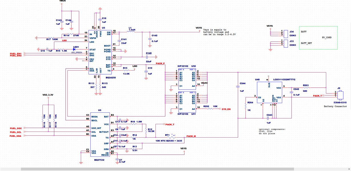
    I try to attach our principal scheme.

    RILIM = 268 Ohm. I've measured it on the board. Nominal should be 267.

    1) Adapter is either laptop USB shell, or HTC 5V@1A

    2) We are using real battery (LG) Cnom =1180 mAh.

    Recommended charging current 0.5C = 580 mA, charging voltage V = 4200 mV

    Measured by FLUKE VBAT = 4100 mV

    3) Charger's registers:

    Status = 0x20

    Reg0 = 0x10

    Reg1 = 0xEC

    Reg2 = 0x8C

    Reg3 = 0x08

    Reg4 = 0x02

    Reg5 = 0xAF

    Reg6 = 0xE0

    Problem: I want to get charging current 550 mA, but I see it 650 mA

    Thank you in advance.

    Alexander.

  • Good day, Joel.

    It looks like it works.
    There was a mistake in my previous reply: value of Reg3 = 0xF8. This register is read-write, so I've written there desired value (0x08).

    The single strange charging current is decreased: it was 540 mA when I started (SoC=5%) and now it is 304 mA (SoC=50%).
    How may I charge with the constant value - it's recommended by battery manufacturer - of 550 mA.

    By the way, when Bypass is disabled, what are the charger's registers values meanings. Part of them have the same values.

    Thank you in advance.
    Alexander.
  • Hey Alexander,

    I am checking with the Gauging team to understand why your charge current. is lower than what is set. 

    When you started (SoC @ 5%), what was your battery voltage? And what was your battery voltage after the charge current decreased (SoC @ 50%)? 

    And each of the register descriptions are listed in the datasheet of the bq24250 here.

    I would focus on:

    Register #1 (memory location 00) = Will reveal any fault conditions

    Register #2 (memory location 01) = Will determine what the input current limit is set to

    Register #4 (memory location 03) = Will determine what the charge current is set to

    Register #5 (memory location 04) = Will which loop is active.

    I would read these registers during 5% SoC and during 50% SoC to see the difference. 

    Also try the same test with the Gauge bypassed; this will determine if the gauge or the charger is controlling this parameter.

    Regards,

    Joel H

  • Good day, Joel.

    As far as I understand, there is certain misunderstanding in charger register's naming:

    - I use Reg0 - Reg6 (from the FuelGauge's point of view)

    - you use Reg1-Reg7 (from the Charger's point of view)

    It may lead us to wrong decisions.

    Meanwhile I discharge our battery - rather slow process - and tomorrow I will provide you proper data of registers and measurements.

    Best regards.

    Alexander.

  • Hey Alexander,

    Yes, it can be a bit misleading. There are two different groups within TI that work on either the charger or the gauge, so the naming convention was mostly given by the gauging team. They were most likely naming based on memory location in the charger. So use Reg0 (in gauge) as memory location 00 in the charger. 

    And I await your results and measurements.

    Regards,

    Joel H

  • Good day, Joel.

    Unfortunately discharging was disturbed - a wire has been disconnected and no one saw it - and the battery still has SoC=34%.

    So we will get desired level of 5% just tomorrow - it's really slow process (about 4% per hour) and here is about 6PM.

    I'm sorry.

    Alexander.

    By the way, one more misleading factor: charger's EN1, EN2 are named EN0, EN1 respectively in the fuel gauge documentation.

    A.

  • Good day, Joel.

    I've performed proper measurements and here is my summary:

    SoC 5% 55%
    Bypass En Dis En Dis
    Current, mA 578 660 489 491
    Voltage, mV 4064 4109 4105 4140
    Chg. Stat. Reg. 0x20 0x20 0x20 0x20
    Reg_0 0x50 -> 0x10 0x50 0x50 0x50
    Reg_1 0xEC 0x48 0x48 0x48
    Reg_2 0x8C 0x8C 0x8C 0x8C
    Reg_3 0x09 -> 0xF8 0x08 0xF8 0x09
    Reg_4 0x82 0x02 0x02 0x02
    Reg_5 0x20 -> 0xAF 0x20 0xAF 0xAF
    Reg_6 0xE0 0xE0 0xE0 0xE0

    Some remarks.

    1. After setting proper Bypass mode, I write Reg3=0x09 (charging current 550mA, current limit 25mA).

    2. In Bypass = En, SoC=5%, Reg0 got values 0x50 -> 0x90 -> 0x10.

    3. When I change Bapass mode, I re-burn FW, so it takes time and SoC meanwhile rises.

    Thank you.

    Alexander.

  • Hey Alexander,

    Thanks for the information.

    Just so I understand better. You are still seeing the charge current issue? You want to see 650mA, but are getting a lower current (here it is 578mA). Is this correct?

    And you are using the Bypass function from the gauge. And here it looks like when you don't bypass, you get the correct current?
    Let me know, that way I can sort through your data here and figure out this puzzle.


    Regards,
    Joel H
  • Good day, Joel.

    The main problem is that I want to charge my battery with CONSTANT current 550mA (it's recommended by battery manufacturers).
    I set this value to the Reg3, according the rules, i.e. I mind base offset of 500mA.
    But in real life I get either high current 660mA, or DECREASING current from 580mA to 100mA etc.

    Thus from my point of view, I cannot manage charging current.
    Furthermore, at the next stage I should be able to charge another battery with the current 2A (2000mA) and I'm not sure at all I will be able.

    Thank you very much for you persistence.

    Alexander.
  • Hey Alex,

    So I have a few questions looking back at your measurements and recorded register settings.

    YELLOW: I am assuming the value to the left of the arrow is what you write? And to the right of the arrow is what the gauge/charger is setting to? (i.e. Programmed Value --> Read Register Value)?

    RED: This register is telling me that you are resetting all the registers to default state. So I'm trying to figure out if you wrote or read that value?

    BLUE: This is indicating that the charger's input current regulation loop is active, meaning charge current will be reduced. This could be tied to your answer for the previous question. Resetting the registers to default would force the device to use the ISET resistor value for charge current, which is 1A based on the resistor value you have set. However, your charge current is still 578mA. 

    GREEN: This is more curious to me. AT 5% SoC, your battery is already at 4.046V, and at 55% it is at 4.105V. The battery charge regulation voltage is set to 4.20V based on the register settings. At this point, you may have already moved from CC (constant current) loop to the CV (constant voltage) loop of the charger. When this loop is active, the charge current WILL decrease until the termination current is reached. 

    How discharged is your battery when you attempt to charge it? I am looking to the gauge learning operation to understand why 5% is at such a high voltage. 

    Could you tell me the specifications of your battery? (i.e Chemistry, max discharge current, max charge current, nominal voltage, maximum voltage, etc)

    Regards,
    Joel H

  • As a side note Alexander,

    Did you perform a learning cycle on the battery with the correct ChemID?

    I say this because the state of charge you are measuring is very unusual. At 5%, I would not expect such a large measured battery voltage.

    Would you be able to provide the .gg configuration file for the gauge along with the information I requested below?


    Thank you,
    Joel H
  • Good day, Joel.

    Today I have returned to the issue and now I am starting from new learning cycle.
    I use BQ27532EVM-656 - evaluation board and EV2400 - auxiliary device to have GUI access to the mentioned evaluation board.
    I configure Key Data Flash Parameters (like ChemID, Design Capacity, Charging voltage, Termination Voltage, etc.).
    And I already have some questions:
    1. How should I choose Taper Current, Taper Voltage and Quit current?
    2. How may I point my wish to have a constant charging current value?

    Thank you in advance.
    Alexander
  • Hey Alex,

    The Taper Current is the same at the termination current. Typically designers set this to C/10 (Battery capacity / 10). However you can set this as low or high as you feel necessary. The value is a tradeoff, though, between full capacity vs cell life (in the long run).

    The Taper Voltage, as I understand it, is a threshold under the battery regulation voltage where the Gauge will determine if the charge needs to be terminated. Default is set to 100mV, which I would say is just fine for your application, unless you wanted to be more conservative, in which case you could increase it perhaps another 100mV. 

    The Quit Current should be less than C/20 for your specific battery, according to the technical reference manual of the bq27531. Read section 6.9.2.2.2 Quit Current of the technical reference manual I have linked here. As I understand it, this is a threshold to where the Gauge will go into a relaxation mode, or detect a relaxation period, where Impedance Track information can be tracked.A battery will relax during different points of charging and discharging when loading/charging conditions change.

    Now to have a constant charging current, I will have to do more research. However, please note that without complete control of your gauge (i.e. standalone running autonomously with a single Data Flash), the gauging algorithm will change the charging current throughout the charge cycle. 

    Regards,

    Joel H