This thread has been locked.

If you have a related question, please click the "Ask a related question" button in the top right corner. The newly created question will be automatically linked to this question.

LM5067 : UVLO / OVLO

Other Parts Discussed in Thread: LM5067

I hope I am making a silly mistake, but im having trouble understanding how the OVLO / UVLO pins work.

the datasheet says that these pins have a threshold that is referenced to Vee.  I am trying to monitor a negative voltage with this part.   I have a -48V supply connected to Vee with a Vcc of gnd.  my goal is to disable when the voltage is outside the window -44 to -52.  but if the OVLO / UVLO pins are referenced to the voltage that is monitored how will the threshold ever be reached?

for example:

Vee= -48V that means UVLO threshold its at -48+2.5 = -45.5V.  if the -48 volt supply drops to -44V( less than the -45.5V threshold)   the threshold is no longer -45.5 is is now -44+2.5 = 41.5..... and so on.  

Am interpreting the data sheet wrong? 

  • Hi David,

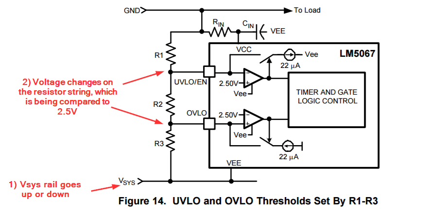
    Thank you for your question. The 2.5V that you're seeing on the datasheet is the reference voltage at one input of  each comparator (one at UVLO comparator and one at OVLO). The other input  is tied to a resistor divider. As the system voltage rail goes up or down, it will change the voltage at the resistor string divider, hence hitting the 2.5V threshold of either UVLO or OVLO. The picture below (page 20 of the datasheet) shows the circuit configuration with the comparators for UVLO and OVLO:

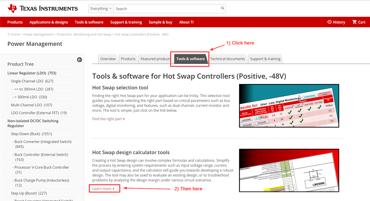
    We have this great calculator tool for the LM5067 which makes it simpler to create a design. You can input your UVLO and OVLO limits and the calculator spits out the values needed for R1, R2, and R3. You can find this calculator tool at www.ti.com/hotswap ==> Click on "Tools and Software" ==> Click on "Hot Swap Calculator Tools".

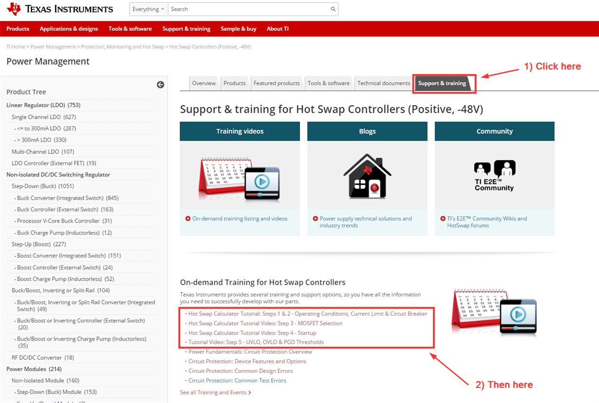
    We also have these great tutorial videos explaining how to fill out each section, row-by-row and what each cell means. The videos are at www.ti.com/hotwap ==> Click on "Support and Training" ==> Click on each video. The videos are broken up into four bite-sized sections (Steps 1 and 2, step 3, step 4, and step 5). The calculator tool is also broken into 5 steps. 

    I hope I made things a bit clearer David, and thank you for using our parts :-)

    Best Regards,

    Aramis P. Alvarez

  • I need tighter control, so i am using option B from the datasheet.  

    can you address this from the datasheet:  if Vsys = Vee, the divided voltage will never reach the threshold, because the threshold is referenced to Vee.  

  • im having trouble posting a response.  please excuse me if this is duplicated.

    Im sorry, but your response did not address my question.

    I need to control both upper and lower UVLO / OVLO so i have chosen option B from the datasheet:

    The calculator you suggested does not show a B option implementation , and the videos do not walk through a negative supply set up.

    the data sheet states that the UVLO / OVLO pins have a threshold of 2.5V above Vee.    

    my question remains:  if i have a -48V supply, the threshold of UVLO = Vee+2.5V = -45.5V

    I want to shut off the supply to the load if the supply dips below -44V.

    but if Vsys (=Vee) drops, the threshold also drops.  So if i have a fixed voltage divider, the threshold will never be met, because the divider is being driven by the same voltage the threshold is referenced too.

  • Hi David,

    The calculator tool has an option B on it. Just hover over the cell and  a drop box will appear (look below):

    The great thing about the calculator tool is that it incorporates the equation from the datasheet and gives you the correct resistances values needed for a give UVLO and OVLO with a hysteresis as well. You will find that this tool does the majority of the work and our customers find it very useful. If something might be confusing, I suggest watching the tutorial videos first as it will greatly decrease the back and forth for explanations. 

    In terms of the VEE voltage, one can look at VEE as a reference ground. The return path is always a higher voltage than the VEE path. I can see how the datasheet can be confusing. What the datasheet is trying to say is that the 2.5V is referenced to VEE (think of it as a ground). But that doesn't change that the 2.5V are a fixed voltage at the comparators and that the UVLO and OVLO pins will be compared to that voltage. Again, sorry for the confusion. 

    I hope the above clears things up a bit. Let me know if you have any other concerns, and thank you for using our parts David :-)

    Best Regards,

    Aramis P. Alvarez

  • i spent some time modeling this using spice, and i was able to make sense of this. thank you.