This thread has been locked.

If you have a related question, please click the "Ask a related question" button in the top right corner. The newly created question will be automatically linked to this question.

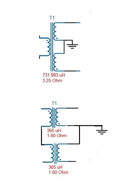
LM2585 Flyback design required a center-tap power inductor - would creating it with 2 separate coupled inductors within the same specs work?

Example schematic:

  • Hello,

    You have run into a common situation where you need additional output windings to achieve multiple outputs.

    You should look at the 6 winding products from Coiltronics - Versapak VP and VPH series. The VPH is usually better for flyback. Many different combinations can be created with these when you series or parallel the windings. They have a nice workbook to assist. This series was designed by an old friend of mine when he worked there. An equivalent lineup was created by Transcomm(sp?) who was later purchased by Midcom IIRC.

  • Hi,

    I would recommend using a center tap transformer as your picture #1. The reason is i am not sure what turns ratio that you will do, is it a step down flyback?

    On the #2 picture, how would you balance the voltage on the primary and hence also the secondary? They will share the same current but you might have to balance the voltage across two windings of coupled inductor. This will cause somewhat a regulation issue on the two center tapped winding. Now another possibility is that you parallel the coupled inductor on the primary and connect the secondary with center tap configuration. This, i am not 100% sure but it's open for experiment. 

    Thanks

    -Arief

  • Thanks for the suggestions, I will investigate those components.
  • Arief,
    It is a step up with a turns ratio of around 6. Trying to create a + and - 100 VDC sources that can supply about 10 ma.

    I agree that the series inductor primary could be unbalances due to tolerances and will look at the Parallel connection of the Primary - thanks.