This thread has been locked.

If you have a related question, please click the "Ask a related question" button in the top right corner. The newly created question will be automatically linked to this question.

LM25010 quick start calculator different to work bench - I get no output current

Other Parts Discussed in Thread: LM25010

Hi all, first post, so go easy :)

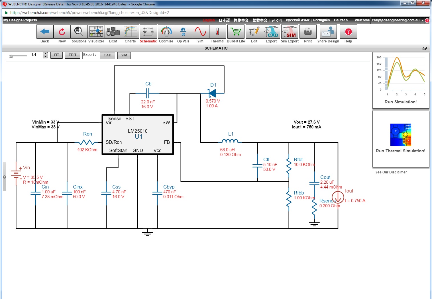
I have used the WEBENCH Designer to create a 33V input 27.6V output using the LM25010. 

Here is the design from WEBENCH link to the design:

https://webench.ti.com/appinfo/webench/scripts/SD2.cgi?ID=185910::power::carl@edsengineering.com.au

When I put those values into the spread sheet calculator it tells me that its not possible, it says the Ron will result in a nominal frequency higher than the max allowed freq, so I have to drop it down to under 278Khz. I dropped it to 186Khz with a 1.2M Ron. Problem is right now i dont have a >130uH coil to test with (as it went from 68uH to 123uH recommended). 

Which design is right? Do I need to increase my coil? why is it taking so long to get up to operating voltage? Why cant it deliver any current?

Currently if it takes a few seconds for the output to come up, it takes a good couple of seconds (Its set for 5mS start up). Then when I connect a 100mA load, it immediately drops to 15V and cannot supply any load current.

  • Hello,

     I followed your link to WB and was unable to iopen the design?

    I am not sure where the Ron value you mentioned above are correct?  I am not sure why the calculator is telling you its not possible?  Can you please post the calculator with your entries so I can take a look. 

    Thanks.

  • I have attached the spread sheet, if you try to use the values in the design below, it will tell you its wrong.

    Maybe try this link again, it worked for me on two computers, it just takes a while to load

    https://webench.ti.com/appinfo/webench/scripts/SD2.cgi?ID=185910::power::carl@edsengineering.com.au

    if now here is a screen capture:

    LM25010QuickStartCalculator.xls

  • Hi,

    Thanks for the spreadsheet. I was still unable to open the webench design. But that aside, I chose an Fsw of 250 kHz and an Ron of 891k. I think we should move on to your issue. Can I have a look at your schematic? Also, please confirm, your issue right now is the Vout takes a long time to come up to set Vout and when you load the output, the voltage collapses? Please confirm. Thanks.
  • Yes, I can confirm the issue is a REALLY slow power up time. Seems fine when i use the 5V design, instant on, current works, but at 27.6V output it works nothing like at 5V.

    I will be changing the design to the other chip with current control as i have to limit the output to 750mA as to not overload my input.

    You can create it quickly using WEBENCH and select 27.6V 750mA wiht 33 to 38V input and it will make the design in a few seconds as shown below.

  • Hi,
    The Webench design looks ok to me. The only potential issue I see with the webench design is the Cout value. You can try increasing Cout from 2.2uF to 4.7uF. I don’t think this is the issue causing your problem. This brings me to my next question. I am assuming you have built up the board? What components did you use on your test board? Can you detail the Cin’s ,Couts , D1 and also the inductor you used and any other component values that deviates from your posted design?

    Thanks.
  • Have you tried putting the values from the WEBENCH example I posted into the spread sheet? It tells you it exceeds the limits... To make it work the coil must be 150uH and the Ron must be around 820Kohm if you use the spread sheet.

    What I have built up on a test board is the WEBENCH example without the snubber circuit and 2200uF input capactior and 47uF output capacitor.
    Here is the coil:
    BOURNS SRU1048-680Y Surface Mount Power Inductor, SRU1048 Series, 68 µH, 1.4 A, 1.25 A, Shielded, 0.127 ohm
    Newark / Element14 link here:
    au.element14.com/.../ProductDisplay

    Here is the diode:
    FAIRCHILD SEMICONDUCTOR SS26 Schottky Rectifier, 60 V, 2 A, Single, DO-214AA, 2 Pins, 700 mV
    Neward / Element 14
    au.element14.com/.../ProductDisplay

    Everything else is pretty standard 50V 0603 parts.
    Input is very stable, no ripple, sitting at 33V.

    In this conflagration It should still "Work" and still deliver 1Amp of current to load and regulate close enough to 27.5 volts. (I am driving a dumb load with this that does not care about noise / stability / ripple as long as its within a few hindered mV my application will work fine).

    With a 47uF output cap it comes up to 27.5V very quickly (I did have 150uF + 2 x 1000uF + small load), but the second I put any load (even 3mA) it will drop several volts. This circuit essentially cannot deliver any current even with a stable input voltage.

    My theory is the WEBENCH is broken for calculating circuit requirements with high Vout values and works fine for lower voltages. I cant imagine to many people want to regulate high voltages like 27.5V.

    According to the spread sheet calculator I should change Ron to 820Kohm and the inductor to 150uH.

    Maybe I will buy this coil and try it? Or is there some other issue?

    This would be the coil I would order to try:
    au.element14.com/.../2329188
  • I am currently unable to get Webench running on my machine. However, the selected frequency in Webench will be different from the spreadsheet calculator and the component selection will vary depending on the selected frequency. Suggest using the spreadsheet calculator to solve issue you are currently facing. Can you send me an up to date schematic of your configuration? The reason why I ask is that you mentioned you are using a 47uF capacitor on the output, yet the Webench design you posted earlier have different value. The output capacitor and the ripple injection scheme are critical for stability. I think you may have a stability issue at the moment? Thank you.