Dear all,
I am designing a device with a single cell Li-Ion battery that is protected by a bq29700 and the SoC is measured by the fuel gauge bq34z100-G1.
I made a first prototype PCB but after seeing carefully, I guess I made a mistake about the schematic.
So, if you look at the 'simplified schematic' for the bq34z100-g1, you can see that the current consumed by the bq34z100-g1 is not taken into account by the shunt resistor! Ok, this current is very low and may be ignored.
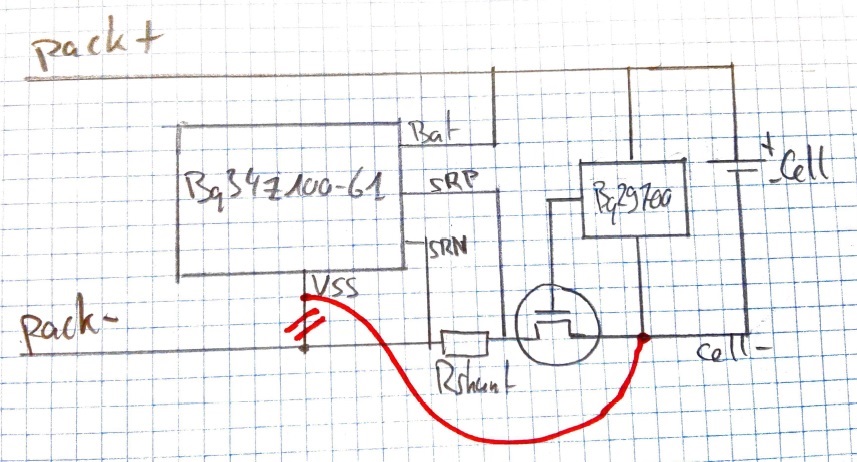
Moreover, with the bq29700, the MOSFET are connected to the Cell- and not Cell+ like in the simplified schematic. So, I just would like to show you my schematic (in a simple way) and it would be great to have your feedback since I will do the final design soon.
As you can see in the picture, my first try (with Vss connected to Pack-) can take into account the current consumed by the bq34z100-G1 which was a good idea. But... after seeing carefully, I saw that the battery voltage measured by the algorithm to estimate the SoC will not be accurate. Indeed, there will be a voltage drop across the shunt resistor, so the fuel gauge will see the shunt resistor (and MOSFET) voltage in addition of the cell voltage.
So, it seems to be a trade-off... but since the current needed by the fuel gauge is extremely low, I guess I must do the modification and connect the Vss pin to Cell- instead of Pack-.
What is you opinion?
Best regards,
Christian


