


Hello,
I am a first-time poster who working on an LED lighting system for my RC truck as an exercise electronics and microcontrollers (I studied EE in college but am now working in systems engineering). Following tutorials seen here ( ) and here (), I chose the TLC5940 driven by a PIC16887 using SPI to send greyscale data. The TLC5940 is driven from the PIC's internal 1 Mhz clock, which uses an interrupt to trigger BLANK every 4096 clock cycles. My first main() function turns each LED on in sequence then turns each off, in a continual loop. So far this implementation is working, except for one significant glitch.
I am having trouble with LED 15: it does not turn on/off when my program activates it, but instead seems to be "linked" to LED1 or LED14 depending on which way the sequence goes. If I increment the channelCounter starting at 0, LED1 and LED15 turn on/off together. If I decrement the channelCounter starting at 15, LED14 comes on when LED15 is turned off and vice versa. It's almost as if LED15's data in my gsData array is wrapping around between position 0 and 15.
I have used MPLAB's debugger to step through my code several times, and confirmed that the greyscale value bit-packing is setting the correctly. I also confirmed with an oscilloscope that BLANK is being triggered every 4.1 ms (a hair over 4.096 ms). The scope is analog so I cannot do much troubleshooting on the serial signal but all other signals appear to be functioning as intended. The issue is easily repeated with no variance so I don't believe wiring or breadboard problems are the culprit. All other LEDs turn on and off as expected.
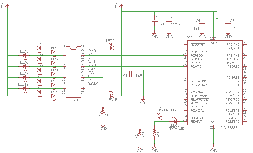
I suspect perhaps the SPI implementation or timing may be the culprit, but have hit the proverbial wall in my analysis. Has anyone else experienced this issue before? If so, what was the cause/solution in your application? Could my bitpacking or SPI implementation still be off-kilter? If you have any suggestions or thoughts I am very much interested in hearing them. I have attached my C code as well as a schematic of the system to this post.
Thanks in advance!
TJ
/******************************************************************************
Project: LED Lighting Control System for RC Vehicles
File: main.c
Purpose: contains main operating functions for lighting system

______________________________________________________________________________
Changes:
10/21/16: General code cleanup, replace button trigger with counter-
			based actuation of LED activation
11/12/16: Removed one shot logic (not needed with auto logic in place),
			added logic to loop LED turning on and off
/******************************************************************************/


#include <htc.h>

__CONFIG(LVPDIS & FCMDIS & IESODIS & BORDIS & DUNPROTECT & UNPROTECT & MCLRDIS & PWRTEN & WDTDIS & INTCLK & BORV21);

typedef unsigned char uint8_t;
typedef unsigned int uint16_t;

// Global Variables
char updatePending = 1;

// Define pin assignments for PIC16F887
#define GSCLK_DDR TRISA
#define GSCLK_PORT PORTA
#define GSCLK_PIN RA6	// Pin 14
#define SIN_DDR TRISC
#define SIN_PORT PORTC
#define SIN_PIN RC5		// Pin 24
#define SCLK_DDR TRISC
#define SCLK_PORT PORTC
#define SCLK_PIN RC3   // Pin 18
#define BLANK_DDR TRISC
#define BLANK_PORT PORTC
#define BLANK_PIN RC6  // Pin 25
#define DCPRG_DDR TRISA
#define DCPRG_PORT PORTA
#define DCPRG_PIN RA7  // Pin 13
#define VPRG_DDR TRISC
#define VPRG_PORT PORTC
#define VPRG_PIN RC0  // Pin 15
#define XLAT_DDR TRISC
#define XLAT_PORT PORTC
#define XLAT_PIN RC7  // Pin 26

// Define port assignment and pin setting macros
#define setOutput(ddr, pin) ((ddr) |= (0 << (pin)))
#define outputState(port,pin) ((port) & (1 << (pin)))

//Initialization code that prepares the registers.
void init(void) {

	// Set output state of registers
	TRISA = 0x00;	// Set PORT A as output
	TRISB = 0x00;	// Set PORT B as output
	TRISC = 0x00;	// Set Port C as output
//	TRISE = 0x00;	// Future Use
	TRISD5 = 1;		// Set pin 5 for button trigger
	TRISD0 = 0;		// Set pin 0 for LED output
	ANSELH= 0x00;	// Turn Analog functions off for PORTB

    // Clear outputs (in case of rouge memory storage)
	PORTA = 0;
	PORTB = 0;
	PORTC = 0;

    // Interrupt Setup for Timer0
	T0IE = 1;		// Enable Timer 0
	PS2 = 0;		// Prescale to 1/16 to fire
	PS1 = 1;		//   every 4096 cycles
	PS0 = 1;
	PSA = 0;		// Select TMRO instead of WDT
	T0CS = 0;		// Select internal clock

    // SPI Setup
	SSPEN = 1;		// Enable SPI mode
	SMP = 1;
	CKE = 0;
	CKP = 0;
	SSPM3 = 0;
	SSPM2 = 0;
	SSPM1 = 0;
	SSPM0 = 0;
	TRISC5 = 0;		// Set as output for assurance of operation
	TRISC3 = 0;

}

// Dot Correction Array
uint8_t dcData[12] = {
	0b11111111, // Channel 11
	0b11111111, // Channel 10
	0b11111111, // Channel 9
	0b11111111, // Channel 8
	0b11111111, // Channel 7
	0b11111111, // Channel 6
	0b11111111, // Channel 5
	0b11111111, // Channel 4
	0b11111111, // Channel 3
	0b11111111, // Channel 2
	0b11111111, // Channel 1
	0b11111111, // Channel 0
};

// LED Greyscale Array
uint8_t gsData[24] = {
	0b00000000,
	0b00000000,
	0b00000000,
	0b00000000,
	0b00000000,
	0b00000000,
	0b00000000,
	0b00000000,
	0b00000000,
	0b00000000,
	0b00000000,
	0b00000000,
	0b00000000,
	0b00000000,
	0b00000000,
	0b00000000,
	0b00000000,
	0b00000000,
	0b00000000,
	0b00000000,
	0b00000000,
	0b00000000,
	0b00000000,
	0b00000000,
};

// Function to set port assignments and
// initial TLC5940 pin states
void TLC5940_Init(void) {
	setOutput(GSCLK_DDR, GSCLK_PIN);
	setOutput(SCLK_DDR, SCLK_PIN);
	setOutput(DCPRG_DDR, DCPRG_PIN);
	setOutput(VPRG_DDR, VPRG_PIN);
   	setOutput(XLAT_DDR, XLAT_PIN);
	setOutput(BLANK_DDR, BLANK_PIN);
	setOutput(SIN_DDR, SIN_PIN);

	GSCLK_PIN = 0;
	SCLK_PIN = 0;
	DCPRG_PIN = 0;
	VPRG_PIN = 1;
	XLAT_PIN = 0;
	BLANK_PIN = 1;
}

// Function to send dot correction values to TLC5940
void TLC5940_ClockInDC(void) {
	DCPRG_PIN = 1;
	VPRG_PIN = 1;

	// Shift dot correction data to TLC5940
	for(char i = 12; i>0; i--){
			SSPBUF = dcData[i];
			while (SSPIF == 0);
			SSPIF = 0;
	}

	// Pulse XLAT now that dot correction is done
	XLAT_PIN = 1;
	XLAT_PIN = 0;
}

// Function to set the greyscale value of a TLC5940 channel
void setTLC5940_Value (unsigned char channel, unsigned int gsSetting) {

	// Swap channels (Most significant byte first for SPI)
	unsigned char index = 0;
	index = 15 - channel;		// Reverse the channel index

	// Determine which array elements need to change
    uint8_t *gsDataPtr = gsData + (((index) * 3) >> 1);
    if (index & 1) {

		// gsSetting starts in middle of byte; set left-hand nibble,
		// increment to next byte and set remaining 8 bits.
        *gsDataPtr = (*gsDataPtr & 0xF0) | (gsSetting >> 8);
        *(++gsDataPtr) = gsSetting & 0xFF;

    } else {

		// gsSetting starts at a whole byte; set the 8 bits first,
		// decriment the pointer and set the remaining 4 bits.
        *(gsDataPtr++) = gsSetting >> 4;
        *gsDataPtr = ((uint8_t)(gsSetting << 4)) | (*gsDataPtr & 0xF);
    }
}

// Interrupt Service Routine
void interrupt ISR(void){

	if(T0IF){	//  Timer for grayscale transmission and latching
		static uint8_t xlatNeedsPulse = 0;

		// Turn on TMR0 LED and turn off LEDs by setting BLANK high
		RB0 = 1;
		BLANK_PIN = 1;

		if (VPRG_PIN) {
			VPRG_PIN = 0;
			if (xlatNeedsPulse) {
				XLAT_PIN = 1;
				XLAT_PIN = 0;
				xlatNeedsPulse = 0;
			}
			SCLK_PIN = 1;
			SCLK_PIN = 0;
		} else if (xlatNeedsPulse) {
			XLAT_PIN = 1;
			XLAT_PIN = 0;
			xlatNeedsPulse = 0;
		}

		// Turn LEDs back on while data is shifted in
		BLANK_PIN = 0;

		// Shift greyscale data to TLC5940 before the next BLANK cycle
		if(updatePending == 1){
			SSPIF = 0;
			char c = 0;
			for (c = 0; c < 23; c++) {
				SSPBUF = gsData[c];
				while (SSPIF == 0);
				SSPIF = 0;
			}
			updatePending = 0;
			xlatNeedsPulse = 1;
		}

		// Turn TMR0 LED off, reset TMR0, and clear interrupt flag
		RB0 = 0;
		TMR0 = 0;
		T0IF = 0;
	}
}

void main(void) {

	// Initialization
	init();
	TLC5940_Init();
	TLC5940_ClockInDC();


	// Enable Interrupts
  	ei();

	// Declare local variables
	RD0 = 0;
	char channelCount = 0;
    char offCycle = 0;
	int gsValue = 250;
	unsigned int counter = 0;

	while(1) {

		counter++;

		// When counter is full, write to the current LED channel
		if(counter == 65535)
		{
			// Set Trigger LED on
			RD0 = 1;

			// Write to current LED channel and set updatePending flag
   			setTLC5940_Value(channelCount,gsValue);
			updatePending = 1;
			channelCount++;		// Increment channel

			// When all 16 channels are set to 250, set gsValue to 0
			if((channelCount > 15) && (offCycle != 1)){
				channelCount = 0;
				gsValue = 0;
				offCycle = 1;
			}

			// When all 16 channels are off, set gsValue back to 250
			if((channelCount > 15) && (offCycle == 1)){
				channelCount = 0;
				gsValue = 250;
				offCycle = 0;
			}

			// Reset counter
			counter = 0;
		}
		else
		{
			// If counter is not done, keep Trigger LED off
			RD0 = 0;
		}
	}
}

