This thread has been locked.

If you have a related question, please click the "Ask a related question" button in the top right corner. The newly created question will be automatically linked to this question.

Replace normal linear regulator with LDO

Other Parts Discussed in Thread: LM317, TLC5926, TL4242, TPS54160, TPS74801

I am trying to redo a certain application for greater battery efficiency. One of the steps I'm considering is using LDOs instead of the "normal" linear regulators.


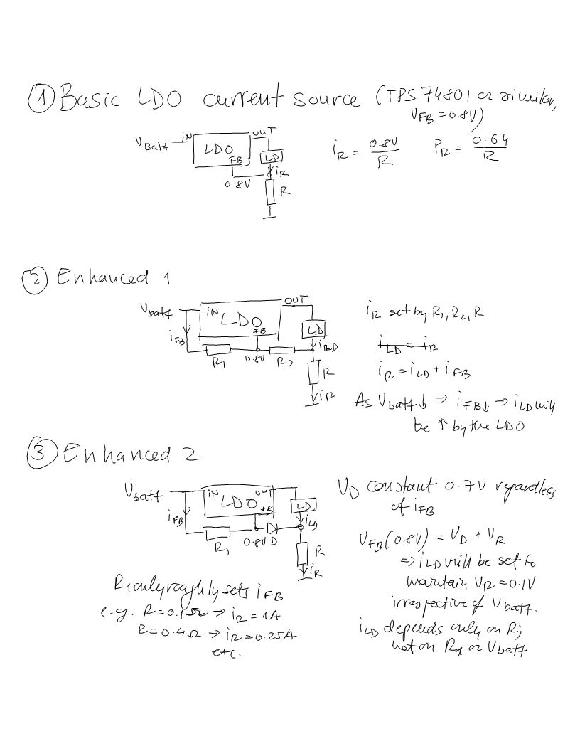
This particular application uses a LM317 in constant current source configuration,  with a resistor between Vout and ADJ to set the current and the load between ADJ and GND. The current requirements are on the order of 0.8-1.3A, selectable by switching the R. 


Now I understand a LDO will not be a drop-in replacement in this application. However, would something like this work: a TPS78601 will have a constant 1.225V between FB and GND (as opposed to LM317 which has the reference voltage between ADJ and OUT). If FB is tied to OUT, the TPS78601 becomes a 1.225V regulator. A resistor R between OUT/FB and GND will set the output current. A load present between the GND of the LDO and the negative pole of the supply will see this constant current (plus the supply current of the LDO, which is a few hundred microamps).


Would this work? I am trying to keep things as simple as possible with this project.

  • Hello Shenle,

    This device change will increase the current source's upper output voltage compliance range due to the lower drop out voltage. This in itself will not improve efficiency. However the operating range of the current source is increased allowing it to work with lower battery voltage.

    As a disadvantage, the current source's lower output voltage compliance range might be reduced as the maximum voltage across TPS78601 must be less than 6V. If the input voltage is 6V or higher, there will be no protection from the current source output being shorted to ground.

    Regards,
    Ron M.

  • Shenle,

    I almost forgot to mention that the voltage from TPS78601 input to ground must be at least 2.7V.

    With the recommended maximum input to ground of 5.5V, this will make a very limited range current source.

    Can you supply more details about the requirements of the current source circuit?


  • Ok here come the details. The load I'm driving is an array of LEDs. Voltage drop across the load of ~2.3V, 2 levels of current (0.8A and 1.3A through switchable resistors). According to my calculations, the change to a LDO will allow me to decrease the battery voltage from 6V to 5V; this being a handheld device, it does make a significant difference.

    And it doesn't look like any of the limitations you list would become an issue; please correct me if I'm wrong.

  • You should also consider the TL4242 for currents up to 500mA or the TLC5926 for currents up to 120mA per channel.   The TLC5926 has 16 output channels that can be paralleled for a total of 1.92A.  See application note SLVA346 for details on how to control the IC without a uP.  Another option is the TPS54160 used as an LED driver.  See application note SLVA374.

  • The TPS device needs 2.7V and the load is 2.3V. That makes 5.0V total which leaves no margin.

    Is the led load terminated to ground or Vbatt? High side termination allows the use of a current sink. This greatly increases the number of compatible devices.

    Regards,
    Ron M. 

  • The TPS54160 output voltage when driving an LED is the LED forward voltage plus the current sense resistor voltage.  In this case, 2.3V+0.8V = 3.1V for the output voltage.  The input voltage to the TPS54160 must be higher than 3.1V for proper regulation.  The TPS54160 is actually regulating a constant voltage across the sense resistor which results in a constant LED current.

    If LEDs are placed in series rather than in parallel, the overall solution will be more efficient.  Note that placing LEDs in series with the TPS54160 requires a higher input voltage or a boost converter. 

  • Unfortunately I cannot put the LEDs in series. The array is fixed, and parallel. On the other hand it's floating as regards to the ground, so it could go on either side.

  • Also, I realize that I haven't exactly clarified what my precise goals are with this project. Number one is reducing the weight by decreasing the number of NiMH cells needed... 4.8V for the input would be ideal since it would allow me to use 4 elements instead of 5. And as a secondary objective, reducing generated heat that needs to be dissipated at the regulator. Battery eficiency only comes third. 

  • Hello Shenle,

    Here is an untested solution using the TPS74801. I included an alternative method for changing the current from 0.8A to 1.3A.

    It should work with VIN = 4V to 5.5V.

    Regards,
    Ron M.

    image.tif
  • Hello Shenle,

    Please send me a drawing of what you mean.  Typically when we want to use an LDO regulator as a current source we use one of two circuits shown in the attached diagram.  In both circuits the current is set by the "current sense" resistor immediately beneath the load.  The smaller the current sense resistor the better the efficiency.  Regarding the top circuit, efficiency can be improved by using an LDO with a lower feeback reference voltage - newer LDOs have references as low as.6V.   The lower circuit affords the best efficiency because the current sense resistor can be somewhat arbitrarily small - at the cost of requiring the pull-up resistor divider connected to another regulated voltage (in this case the Vin voltage).

    Regards

    Bill

    Current Source LDO.doc
  • Thank you for your suggestions!


    Ron, that's an interesting design. Well worth a try.


    Bill, I'll give that last circuit a try. A couple extra resistors for the sake of saving a watt is well worth it.


    Thanks again!

  • The last design has the following problem: if Vin is not stabilized, as the battery life runs out Vin will drop, thus current through the divider will drop thus the LDO will try to compensate by increasing the output current. This is undesired and even dangerous.

    See my solution for this problem in the third panel attached. Basically I am stabilizing part of the voltage applied to FB, and letting the only variable be the voltage drop on R, dependent on the load current.