This thread has been locked.

If you have a related question, please click the "Ask a related question" button in the top right corner. The newly created question will be automatically linked to this question.

TPS65130 VPOS is always zero and VNEG is oscillating

Other Parts Discussed in Thread: TPS65130

Hi,

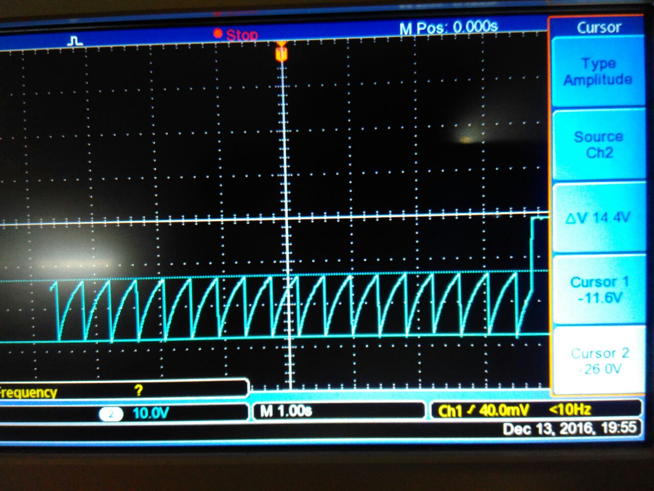
I am evaluating TPS65130 as a power supply in one of my projects, the VPOS  is always zero but VNEG is as calculated.

 The schematic is exactly same as in Fig.8 of the datasheet. The following contains the details of the parts used,

Q1 -> IRF9540

D1,D2 -> ss36-e3/57t  Schottky diode

L1, L2 -> 4.7uH (www.abracon.com/.../ASPI-0403.pdf)

C6,C5 -> 10nF 

R1,R3 -> 1M ohm

R2,R4 -> 100K ohm

C9 was earlier open, later i added 22pF capacitor. But no output from VPOS.

C4 was totally 22uF earlier, later I removed it. C4 is open.

C10 is open.

All  other values are same as in FIG.8

Observations:

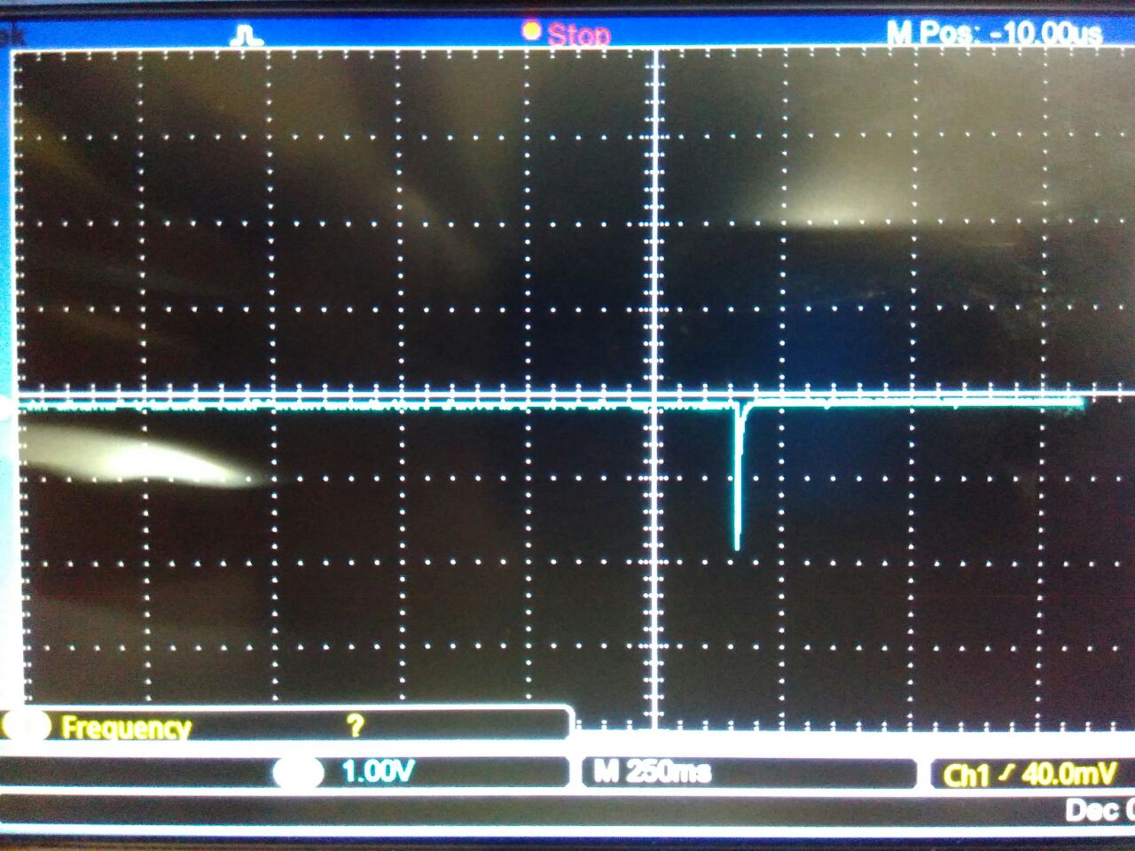
After Powering ON, The P-channel Mosfet starts heating UP. BSW pin always LOW.

BSW pin always LOW.

Where have I gone wrong?

  • Hello Tejas,

    Would you please share your schematic and layout? I am asking you for friendship there we can discuss privately if you do not want to share it here.

    Best regards,
    Brigitte
  • Hello Tejas,

    After checking the datasheet of IRF9540, I wonder if the BSW pin is able to drive this transistor fully on. Would you please check if the boost converter is able to start when you short out the PMOS from Source to Drain?

    Best regards,
    Brigitte

  • Hello Brigitte,

    I will get back to you after I bypass IRF9540. I just want to know what is the expected result by bypassing the mosfet.

    I also want to the operation of the inductor when the p-mosfet is removed?

    How will the output voltage differ when the output capacitors (C4 and C5) are removed?

    I have connected C9 and C10 with 18pF capacitors. But the suggested values are 6.8pF and 7.5pF. Will this change in value contribute to Boost converter not starting?

    Regards,
    Tejas S J
  • Hello Tejas,

    Due to the fact that you mentioned the heat of the MOSFET, I expect that the TPS65130 is not able to drive the MOSFET on. The used MOSFET is a power MOSFET, which needs a high current to turn on. I think the IC is not able to achieve such a high current. If you bypass the MOSFET the boost converter is not longer dependent on the MOSFET to turn on, so you can check if the MOSFET is the problem.

    I do not understand the question about the operation of the inductor when the MOSFET is removed. Please reword that I can understand.

    Why do you want to remove C4 and C5?

    The values of the capacitor on the feedback node of the boost converter will not influence the startup, it could influence the stability after it started.

    Best regards,

    Brigitte

  • Hello Brigitte,

    1. Bypassing the IRF9540 has worked. The VPOS is as calculated.

    2. There is one more problem now, VNEG is not starting.

    When I was populating a new board, I didnt connect the C4 and C5 capacitors and powered on the regulator. The Vpos and Vneg were around +3.7V and -3.7V. Later I connected 4.7uF x 2 for C4 and 4.7uF for C5 after this point the Vneg  is not starting up.

    The output in 'OUTN' pin is always zero.

    This is how the Vneg varies during the startup:


    Please help.

    Regards,

    Tejas SJ

  • Hello Tejas,

    The part will not work with C4 and C5 not connected. It could even happen that the part is damaged. The first test I would recommend is exchanging the IC to make sure it is not damaged.

    Even 4.7uF is most probable too small for the IC to regulate properly.

    Why did you not populate C4 and C5?

    Best regards,
    Brigitte

  • Hello Brigitte,

    I am facing an issue in the negative part of the power supply, the output is oscillating. The picture posted down is the VNEG voltage. The OUTN pin is always zero. I have used two 10uF capacitors in parallel for C5.

    The  VNEG was stable earlier when the VPOS was not working, so I know that the board has no issue but may be some other parameter which I am not considering

    Please help.

  • Hello Tejas,

    What do you mean with OUTN is always zero? OUTN is the switch node of the buck-boost converter, so if this is always zero, there should not be any negative voltage on the output.

    Please turn off VPOS with the ENP signal and check if the output is showing the same behavior or if it is now stable again.

    Whenever you check out a converter and see issues there, please always check the input voltage, the compensation as well as the feedback if you observe something strange.

    Best regards,
    Brigitte