This thread has been locked.

If you have a related question, please click the "Ask a related question" button in the top right corner. The newly created question will be automatically linked to this question.

TPS40210, early overcurrent shutdown

Other Parts Discussed in Thread: TPS40210

Hi,

I experience some problems with the TPS40210 regarding the overcurrent shutdown. The problem is very similar to that posted by Thomas Schmit on Apr. 30, 2013 "TPS40210 Current Output Too Low / Early Overcurrent Shutdown".

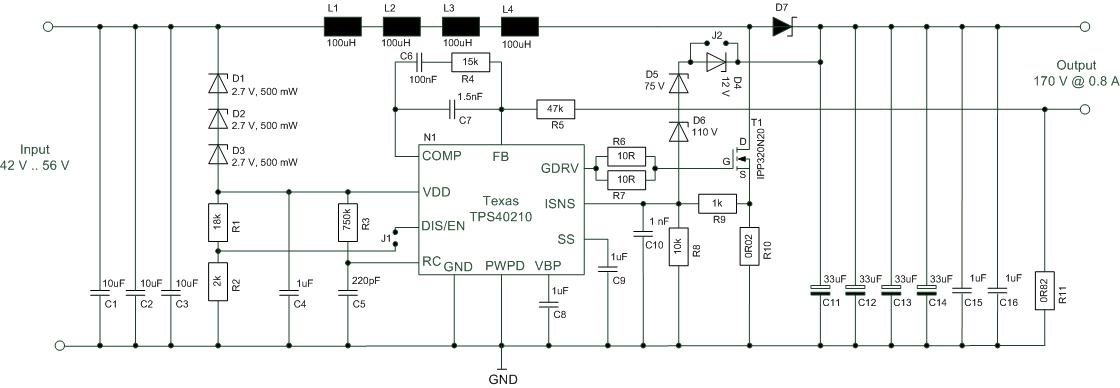
My circuit works as a current source and therefore I mainly used the design example of the TPS40210 data sheet on page 32 "35 V LED driver" with some modification to meet my requirements on input / output voltage and output current. Here is the schematic

The problem is that I cannot reach the required output voltage. Using a modifiable load (resistor) I can just reach about 115 V. Up to that point everything works well and I get my required output current of 0.8 A. But when I further increase the load resistor the converter enters the hiccup mode.

When I decrease the output current to 0.6 A (by changing R11 to 1R1) I can increase the load resistor up to an output voltage of approx. 160 V. But then again the converter shuts down. In both cases the input current reaches almost 2 A. But with R10 = 25 mOhm a peak current of up to 6 A should be possible before the converter shuts down.

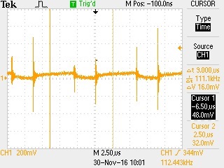
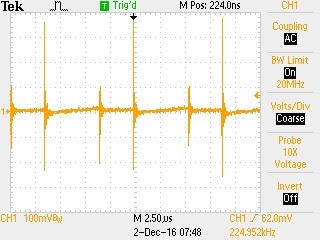
I already tried to decrease the current sense resistor to 19 mOhm but unfortunately with no effect at all. When I measure the ISNS pin with an oscilloscope I can see that the voltage just reaches about 80 mV which is far away from the shutdown threshold. Though the voltage spikes with every MOSFET switching make me suspicious and I wonder whether the problem could be related to that. Here is the screenshot:

On the other hand these spikes are there with more or less the same level also in situation where the converters works well.

I really appreciate any hints or recommendations.

Thanks so far

Thomas

  • Hi Thomos,

    Can you check if C10 in your design is close enough to ISNS pin?

    How is C10 connected to the GND? Is it connected to a noisy ground?

    Can you increase C10 value to see if it helps on the issue?

    Thanks

    Qian

  • Hi Qian,

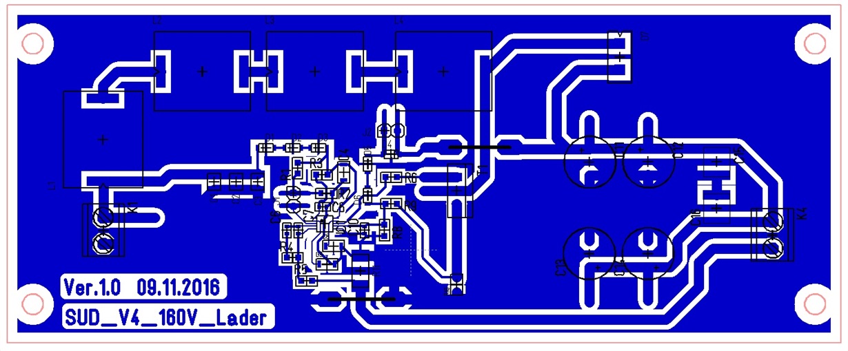
    thanks for your fast reply. I already tried to increase C10 to 6.8 nF which is more or less 10 times the calculated value but unfortunately without any success. In fact I also tried to decrease C10 just to see what happens but also this change doesn't have any impact on the circuit behavior (it does not even get worse). I think C10 is located pretty close to the TPS40210 but the whole layout might be not optimal because this is just a first prototype we assembled here in the office as a "proof of concept" not a professional layout yet. Here is a screenshot of our layout.

    How can I check whether we have a noisy ground? And what about the spikes on the ISNS line. Do you think that they might have an impact on the described behavior?

    Thanks in advance for your support.

    Thomas

  • Hi Thomas, 

    The issue could be related to the voltage spike on ISNS pin. 

    Can you remove D6 and to see if the spike on ISNS pin is caused by D4-D5-D6?

    Also, can you check if VIN pin (pin 10) voltage and BP pin (pin 9) voltage is stable? Is there high noise/ripple on these two pins?

    Meanwhile, can you send the layout design file to below address, so I can take a close look?

    Q-CHEN AT TI.COM

    Thanks

    Qian

  • Hi Qian,

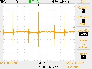
    thanks again for your fast reply. I removed D6 as you suggested but with no success. I also removed R8 and this doesn't help either. The ripple at Vdd (Pin 10) looks like this:

    And the ripple at BP (pin 9) is more or less the same:

    I will send you the layout files to your e-mail address as requested.

    One additional question: The TPS40210 has a thermal pad at the rear side. Is it necessary to connect this to any potential e. g. GND? Currently this pad isn't connected at all.

    Thanks for your support

    Thomas