This thread has been locked.

If you have a related question, please click the "Ask a related question" button in the top right corner. The newly created question will be automatically linked to this question.

Drive power mosfet using UCC21520

Other Parts Discussed in Thread: UCC21520

Hi everyone,

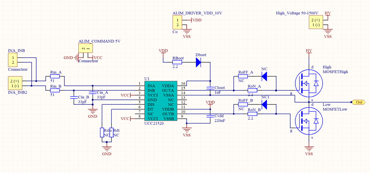
We are trying to do a H-bridge using UCC21520 and power mosfet STFW3N170 VDSmax 1700V -> datasheet.

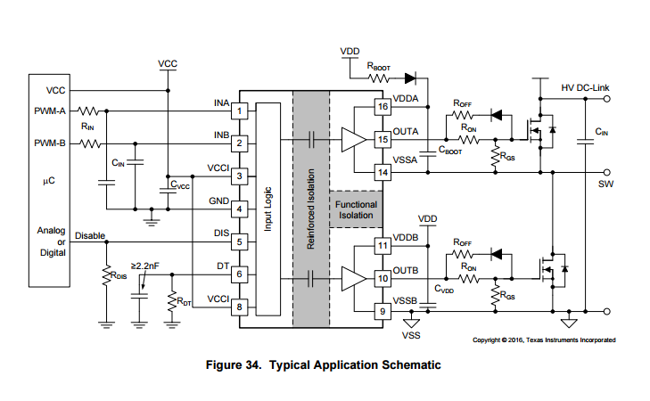
There is a typical application in the datasheet to do a half bridge:

We didn't put Rds and Rdt, RoFF_A+Diode, RoFF_B+Diode.

The problem is that we are not able to trigger correctly the upper mosfet. The lower mosfet works well depending on INB's level.

The logical side is supplied with 5v, the driver's supply is separeted with 20V and the HighVoltage is 50V, the VSS of the HV and driver are conenected together.

It seems that when we put a 1 logic in INA we can see the bootstrap capacitor release its charge into the gate but it lasts like 1ms then the mosfet become locked again. 

Should we put a resistive load in output anytime to have a small current through the output line?

I know that the Bootstrap capacitor + Diode are very important but I don't really understand how it should work is this circuit, we took a random value 1uF with 2.2Ohm to limit the current and a shocky diode rated for 600V

Thank you very much

  • Hello Alexis,

    Thanks very much for your detailed description.

    In bootstrap configuration, INB shall be turned-on to refresh the Cboot to make sure A channel work well. If you only apply INA without applying INB. There will be no path to charge the Cboot if you connect nothing from OUT to VSS. Would you please help confirm how the INA/B settings are for your test?

    Best regards,

    Wei

  • Thank you very much for your answer.

    You are right, in our test we only applied on INA, INB were grounded.

    For our application we want to charge a capacitor with a high voltage in both direction, so a H-bridge is required. For our first test we just use a Semi H bridge to try to charge a capacitor. As you said we need to charge the Cboot but our capacitor connected to the output will not create a path to charge Cboot. So what is suggested? Should we put a big resistor in parallel to our capacitor?

    And finaly, the schematic should be like this:

    Suppose that  OUTA_left and OUTB_right are trigger with the same signal, same for OUTB_left and OUTA_right.

    You said we are obliged to control INB to charge the Cboot but in our case we want to charge Uc so trigger OUTA_left and OUTB_right during around 1 second.

    Thank you very much

  • Alexis, You are very welcome.

    Thanks again for your explanation and I understand your concern.

    1. This circuit is trying to parallel two capacitors (DC bypassing cap and the cap between two bridge) with different voltage. It vialates the circuit fudamental law. There will be uncontrollalbe current if this circuit is used. I mean the current will be skyhigh and might damage the part. I suggest to rethink the circuit topology or limit the current with a resistor.

    2. What will be the charge discharge frequency for the "Uc"?  or how long you wish to hold the "Uc" when it is high or low?

    I will try to discuss the options to recharge the Bootstrap when the above questions are addressed.

    Best regards,

    Wei

  • Thanks Wei

    We want to do around 10 charges pers second (10Hz), as you can see that's very low.

    or how long you wish to hold the "Uc" when it is high or low?

    Well the value of the capacitor is not well defined. The time of holding will depend of the current's limitation of our high voltage and the resistor Rds.

    I suggest to rethink the circuit topology or limit the current with a resistor.

    Which resistor are you talking about?

    Thank you

  • Thanks, Alexis,

    Good to know the frequency. How fast you plan to charge the capacitor from negative steady state to positive steady state? in ns, us, ms?
  • Hum we are supposed to discharge the capacitor in another circuit when the capa is fully charged. So normaly it's not supposed to switch from negative steady state to positive steady state or vice versa.
  • Thanks. So how fast you plan to charge the cap to negative rail or positive rail, in ns, ms, us?
  • Well, we want to discharge every 100ms so  we have less than 100ms to charge them but 15 ms or 55ms it doesn't matter.

    Thank you