This thread has been locked.

If you have a related question, please click the "Ask a related question" button in the top right corner. The newly created question will be automatically linked to this question.

TPS2490 Supply current when disabled

Other Parts Discussed in Thread: TPS2490

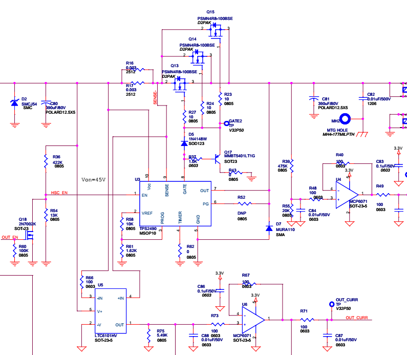
I am using TPS2490 driving three MOSFETs in parallel at the output of a DC/DC converter (30V).

I measured the current drawn by the TPS2490 circuit when EN pin is held low (0V) and it is around 500uA, while the datasheet says 90uA typ and 250uA max.

Why the higher supply current when in shutdown mode?

  • Hi Kiril,

    Welcome to E2E. Let's see if we can figure this out. Would it be possible for you to attach a picture on how the current is being measured? Also, I'm not sure what else is attached to our device. Attaching another picture of your schematic would be helpful as well.

    One more note, the datasheet states that the 250uA max rating  is when Vcc=Vsense=Vout. Thank you for considering our part in your system Kiril :-)

    Best Regards,

    Aramis P. Alvarez

  • Hi Aramis,

    I measured the current by eliminating and taking into account all other circuits connected. I am using TPS2490 to disconnect the output of my boost converter from the load.

    When the input voltage is applied, but the converter disabled, TPS2490 is in UVLO and blocks the input voltage from the output. In that case, the Vcc and SENSE pins are at 25V, while the OUT pin is at 0V. In that situation my estimate is that TPS2490 draws around 500uA, which is higher than the spec in the datasheet.

  • Thank you for your comments above. Could you send me a screenshot of your schematic?

    Best Regards,
    Aramis P. Alvarez
  • Hi Aramis,

    See below the section utilizing TPS2490 controller. The CSA U5 has been removed for the test.

  • Hi Kiril,

    Thank you for the screenshot of your schematic. I went ahead and measured the current on an EVM board, and it was around 125uA (within the specs). I believe I know why you're measuring 500uA of current. There are two current paths to ground that might be adding up to 500uA.

    1) When the FET (Q18) is turned on, there's current flowing through R36 to GND. This produces an extra 45V / 422kohms = 107uA. 

    2) When VCC is powered, the 4V regulator at the VREF pin is activated (even with enable low). The amount of current flowing through R58 and R61 is 4V / 11.62kohms = 344uA. 

    If you would like to decrease the current from 2), increase the resistance values of R58 and R61 by 10x.  If you would like to also decrease the current from 1), increase the resistance value to around 2Mohms. I hope this helps.

    Also, I'm not sure if you know this but we have these great calculator tools for our parts to make sure the design is very Robust. You can find it by going to www.ti.com/hotwap ==> click on “Tools & software” ==> then click on “Hot Swap design calculator tools”.

    We also created these video tutorials on how to fill out the hot-swap design calculator spreadsheet. They explain cell by cell what each one means and how to enter the correct value. The videos are at www.ti.com/hotswap ==> Click on “Support & Training” tab.


    Best Regards, 

    Aramis P. Alvarez


  • Thanks, Aramis!
    I assumed that the reference is off, and I think I even measured it to be off, but I just verified that it is on when the controller is disabled.
    Thanks for the suggestions.
    Kiril