This thread has been locked.

If you have a related question, please click the "Ask a related question" button in the top right corner. The newly created question will be automatically linked to this question.

BQ24133's charge current range

Other Parts Discussed in Thread: BQ24133

    In my BQ24133 application, the CELL PIN is floating, Rsr = 10 mohm, Viset = 1.75V, the charge current should be 875mA. However, when I use a 10V-2A power supply to charge a battery(voltage between 7V and 8.2V), the current showed is far less than 875mA(685mA or 710mA or so for different batteries with voltage between 7V and 8.2V). Is this normal?

    I think BQ24133 works in CC charge stage when the battery voltage is between 7V and 8.2V, and the charge current should be a relatively steady value. 

    Additionally, from the specificatios, charge current regulation accuracy is as follows:

Should I think the charge current for my case is between 875mA*(1-25%)=656.25mA and 875mA*(1+25%)=1093.75mA? If so, the chip has a poor charge current accuracy.

  • Hi,

    I think there are some differences in the way we are calculating fast charge. If Viset is 1.75V, and Rsns = 0.01 Ohm, then Ichg is calculated as:

    Ichg = 1.75/(20*0.01) = 1.75/0.2 = 8.75A, which is well outside of the charge current spec. I am not sure why you would be seeing 1/10th of that value, unless you are in precharge or the charger automatically "folds back" the charge current when it detects it is too high (i have never seen this before, though).

    It does seem to be the case that the charge current accuracy is not guaranteed to be very accurate at the charge current you are requesting. At 0.5A, the spec is +-20%. At 2.5A, the spec is +-8%. Since the minimum recommended charge current is 0.6A, I would guess that this current is required for +-10%, since this is what we usually spec devices for.
  • i'm really sorry that i've made a mistake. What I want to say is that Viset is 0.175V, but I spelled it as 1.75V. If Viset is 0.175V, the typical charge current should be 875mA. But I get a result far less as mentioned before.
    Vsrp-srn is 875*0.01=8.75mV, then the charge current accuracy is between +/-8% and +/-20%? Is 685mA or 710mA a correct result?
  • I would guess that for that this charge current, accuracy would be between 10% and 15%. However, the accuracy you are seeing is pretty alarming.

    I am also concerned that it seems to be battery-dependent. This definitely should not be the case - the control loop of the charger should be able to maintain the correct charge current.

    For this, I have two questions:
    1) How is your layout for the Kalvin Connections for SRP/SRN? You could have noise coupling in, or if the traces are not matched, the charger will effectively see this as a larger sense resistor than you really have.

    2) Does your battery have any gauging/protection? I am wondering if that is somehow interfering.
  • Hi,

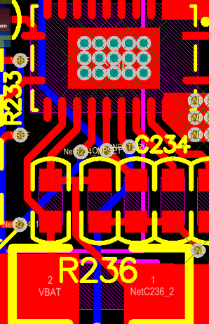
    My layout is as shown below

    R236 is the sampling resistor. I think the layout is close to Kalvin Connection pattern. The VBAT and NetC236_2 connections don't have the exactly same length. But I don't think there is such a serious impact, as these are two low-current paths. Is my understanding correct?

    There is no gauging or protection for my battery. For the normal case, in the CC stage the charging current will be a steady value or  vary in the accuracy range, e.g +/-15%, as the charging progresses?

    Thank you!

  • For your last question - the charge current should be a steady value in CC mode. The charger senses the resistance between SRP/SRN, and "expects" a certain sense resistor - usually 10mOhm. At a very high level, it uses Ohm's law to say "I have XXX charge current", and it will feed that signal into a feedback path. This current mode feedback should maintain a very steady current. Once the control loop senses the regulation voltage, it will "give up" regulating charge current. The charger maintains the voltage just like a normal DC-DC converter, and let's the battery/trace impedance determine charge current.

    As far as the layout goes - I think that the mismatch is large enough to cause a difference. You are correct in the fact that little current flows (the pins have some leakage), but the trace impedance will play a large factor. In this case, you don't need much current to cause problems.
  • I will try to modify my layout and see if the problem can be solved. Thank you very much!